Section 04 ENGINE
Sub-Section 05 (CDI SYSTEM)
04-05-7
NOTE : The following procedures can be
done without removing the engine from
chassis.
CLEANING
Clean all metal components in a non-ferrous met-
al cleaner.
CAUTION : Clean stator and magneto us-
ing only a clean cloth.
DISASSEMBLY
3, Magneto Flywheel Nut
To gain access to magneto assembly, remove the
following parts as needed on different engines :
– muffler
– rewind starter with oil injection pump
– starting and V-belt pulleys
To remove magneto flywheel retaining nut :
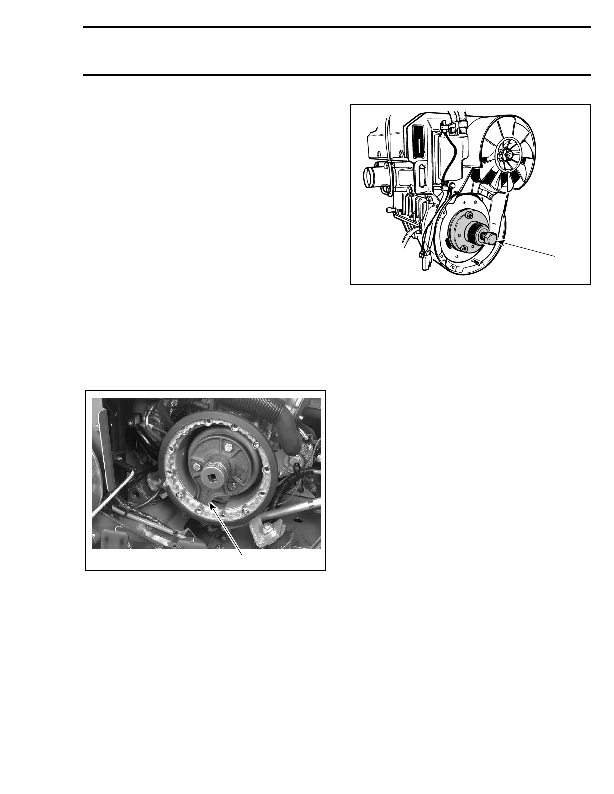
Install magneto puller ring (P / N 420 8760 00).
TYPICAL
1. Tab in magneto housing opening
Remove magneto flywheel nut.
NOTE : To correctly remove a threadlocked
fastener it is first necessary to tap on the fas-
tener to break threadlocker bond. This will elimi-
nate the possibility of thread breakage.
2, Magneto Flywheel
To remove magneto flywheel, install the suitable
puller as shown.
TYPICAL
– Tighten puller bolt and at the same time, tap on
bolt head using a hammer to release magneto
flywheel from its taper.
REPAIR
4,9, Trigger Coil and Screw
To replace trigger coil :
– Disconnect trigger coil wire (RED).
– Remove grommet from crankcase where trig-
ger coil wire exits magneto housing.
– Remove retaining screws.
– Remove trigger coil and carefully pull wires.
– Install new trigger coil and other parts re-
moved.
Adjustment
Whenever the trigger coil or the magneto fly-
wheel is removed or replaced, the air-gap be-
tween the trigger coil and the flywheel protrusion
must be checked and adjusted. The purpose of
this adjustment is to obtain the minimum clear-
ance between these parts – without touching at
any RPM – so that the trigger coil produces its
proper electrical output. Ignition timing must also
be checked.
Proceed as follows :
1. Rotate flywheel so that the protrusion aligns
with trigger coil.
2. Using a feeler gauge of 0.45 mm (.018 in) to
0.55 mm (.022 in) thick, check air-gap between
center pole of trigger coil and flywheel protru-
sion.
'
A06E22A
1
'
A09C37A
420 8760 65
420 8760 80
 Loading...