Section 07 REAR SUSPENSION
Sub-Section 03 (IMPROVED C-7 SUSPENSION)
03-03-2
REMOVAL
NOTE : To prevent cross shaft from turning
when unscrewing screws assembled with
threadlocker, proceed as follows :
– Loosen one screw then retighten.
– Remove the other screw.
– Remove the first one.
CAUTION : Close fuel shut-off valve be-
fore lifting vehicle.
Lift rear of vehicle off the ground about 850 mm
(33-1/2 in).
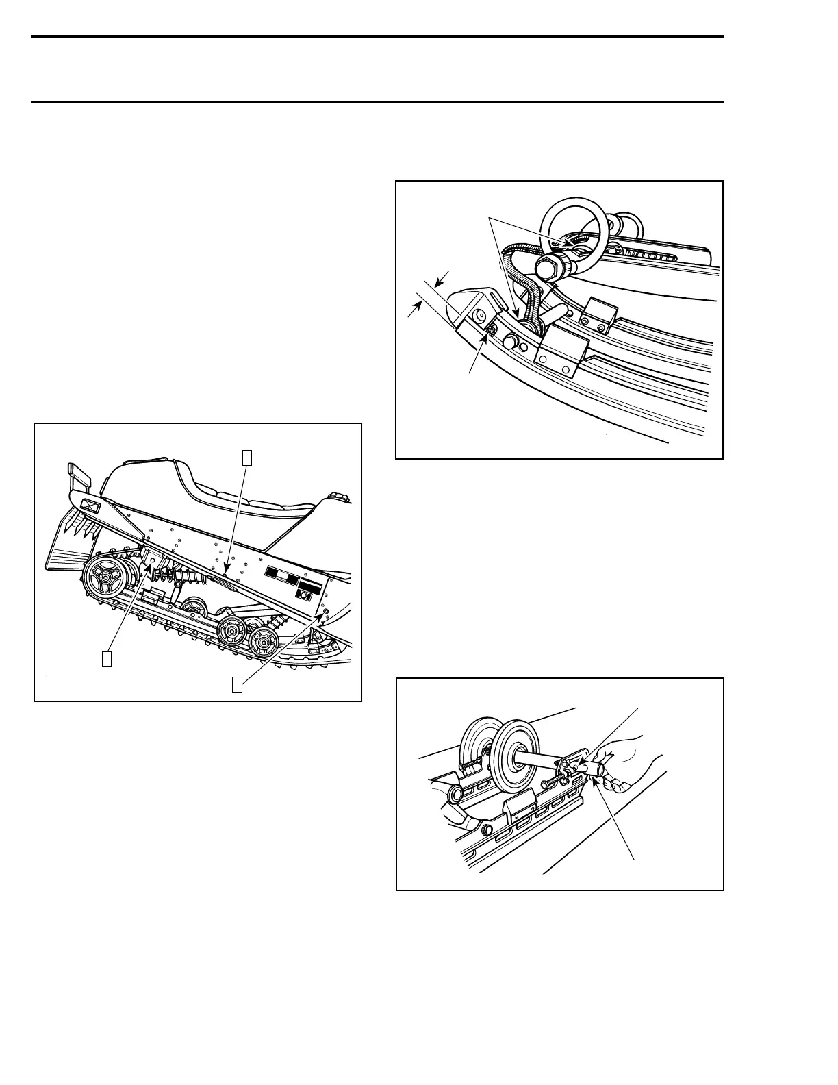
Unscrew 6 screws retaining front arm, shock piv-
ot and rear arm to frame in the illustrated se-
quence.
TYPICAL
1. Remove suspension.
DISASSEMBLY AND ASSEMBLY
20, Stopper Strap
Inspect strap for wear or cracks. Check seams.
Replace as required.
At installation, slide washers no. 19 and spring
clamps no. 18 on axle no. 17 until stopper strap is
in line with its tensioner mounted on front arm.
See illustration below.
1,2,3,4, Slider Shoe, Bolt, Washer and
Nut
To replace a worn shoe, remove the front bolt and
stop nut, then slide the shoe rearward out of the
runner.
NOTE : Slider shoe minimum thickness : 10
mm (25/64 in).
TYPICAL
1. In line
2. Front screw and nut
A. 10 mm (25/64 in)
CAUTION : Slider shoes must always be
replaced in pairs.
5,6,7,8,9, Rear Axle, Long Spacer, Short
Spacer, Outer Spacer and Screw
At assembly, center idler wheel must be offset to
the right (opposite side of stopper strap).
Position outer spacer as shown.
1. Rear axle hole
2. Outer spacer
CAUTION : It is important to properly po-
sition the outer spacer. Disregarding this
notice might cause rear axle failure.
Position hole on rear axle forward.
'
A06F05A
1
2
3
'
A06F06A
1
A
2
A06F07A
1
2



 To Next Page