Overview
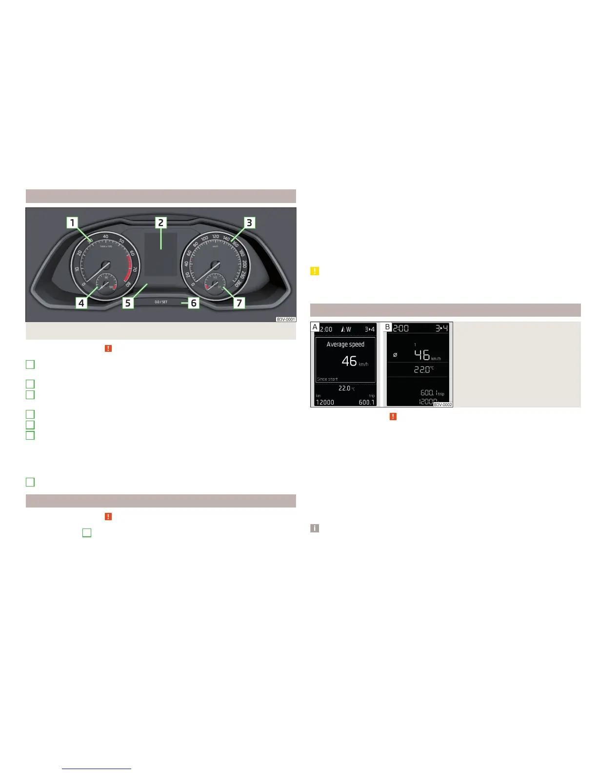
Fig. 22 Instrument cluster
Read and observe on page 28 first.
Engine rev counter » page 29
▶
with warning lights » page 31
Display » page 29
Speedometer
▶
with warning lights » page 31
Coolant temperature gauge » page 30
Bar with warning lights » page 31
Button for:
▶
Setting the time » page 31
▶
Reset counter for distance travelled (trip) » page 31
▶
Displaying the distance and days until the next service interval
» page 49
Fuel gauge » page 30
Revolutions counter
Read and observe
on page 28 first.
The tachometer
1
» Fig. 22 on page 29 shows the actual engine speed per
minute.
1
2
3
4
5
6
7
The beginning of the tachometer red scale range indicates the maximum per-
mitted speed for an engine that has been driven-in and has reached operating
temperature.
You should shift into the next highest gear before the red scale of the revolu-
tion counter is reached, or select mode D on the automatic gearbox.
The gear recommendation is important to note in order to maintain the opti-
mum engine speed » page 42.
CAUTION
The pointer of the tachometer must reach the red area for only a short time -
there is a risk of engine damage!
Display
Fig. 23
Display types
Read and observe on page 28 first.
Display types » Fig. 23
MAXI DOT display
Segment display
The following information will be displayed.
▶
Exterior temperature information
▶
Distance travelled » page 31
▶
Time » page 31
▶
Warning lights » page 31
▶
Information system data » page 41
Note
Depending on vehicle equipment, the MAXI DOT display can be either mono-
chromatic “(black and white)” or colour.
29
Instruments and warning lights

 Loading...