156
SJ30AJE, SJ30ARJE196274AF
Section 5 – Procedures Base
5.6-4 Electronic Tilt Switch Setup
Procedure
The following information is supplied for replacement
or reprogramming of the electronic tilt switch. Also
included are test and verification instructions. Follow
the appropriate procedures below.
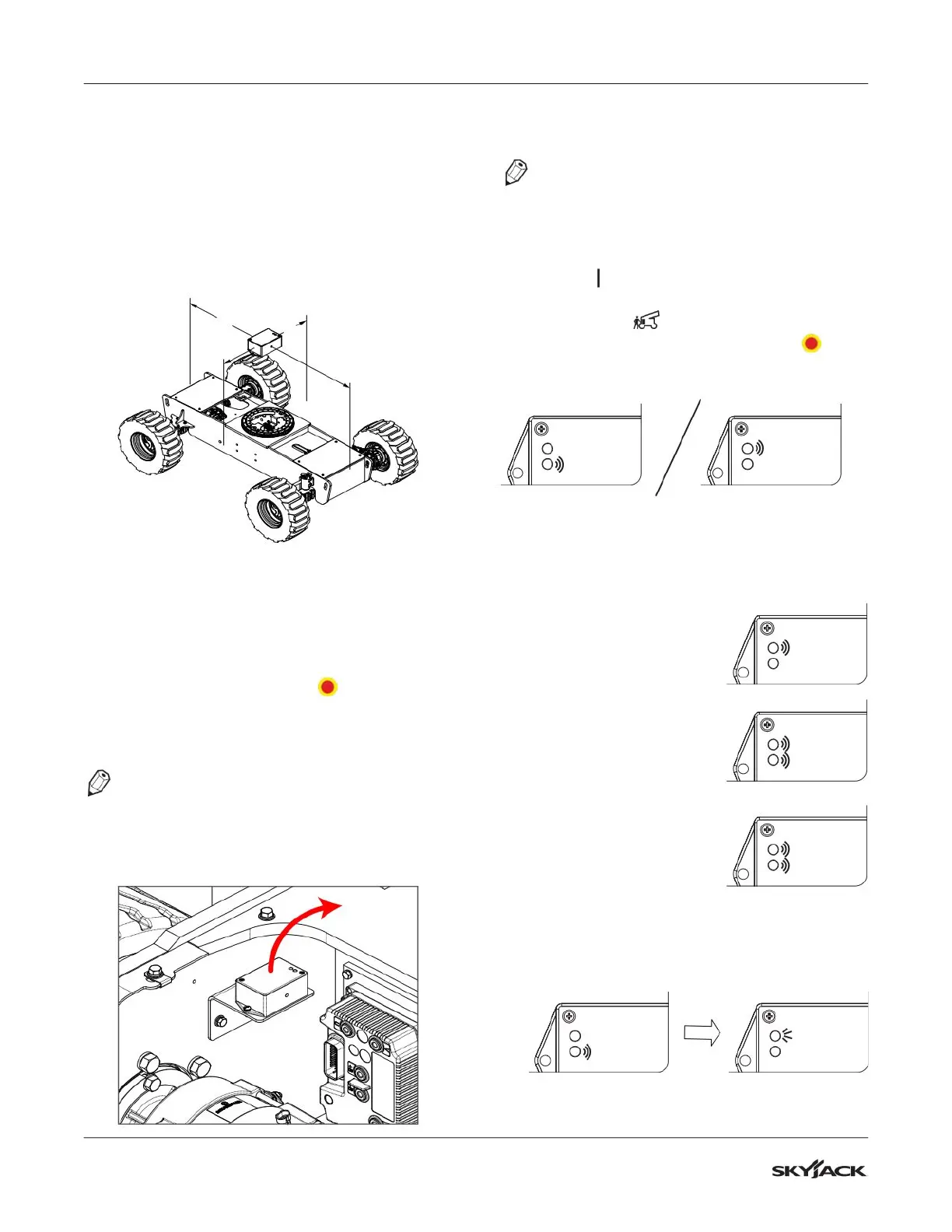
Tilt Switch Replacement
Y AXIS
X AXIS
1. Ensure the MEWP is parked on a firm, level
surface.
2. Fully lower the platform and retract the fly
boom.
3. Chock or block the wheels to keep the MEWP
from rolling forward or backward.
4. Push in the emergency stop buttons and
disconnect one of the main power connectors.
5. Disconnect the tilt switch from the 4 pin
connector.
NOTE
Make sure the part number of the old tilt switch
and the new tilt switch are the same.
6. Remove the old tilt switch from the mount.
7. Install the new switch onto the mount and
connect the switch plug to the 4 pin connector.
NOTE
The tilt circuit is only powered when the controls
are powered up.
8. Turn the main disconnect switch to the ON
position .
9. Turn the base/off/platform key switch to the
base position .
10. Pull out both emergency stop buttons .
11. Verify the switch is powered (the red or green
LED will be continually blinking).
Red LED
Green LED
Red LED
Green LED
12. Program the tilt switch:
a. Press and release the set up button 3 times.
Observe the LED flash codes as shown
below.
b. Only the red LED
blinks for 4 seconds.
Red LED
Green LED
c. Both LEDs flash for 1
second.
Results: The switch is
learning the new zero
position.
Red LED
Green LED
d. Both LEDs turn on
solid for 1 second.
Results: The new zero
position has been
learned.
Red LED
Green LED
e. The green LED flashes and then the
red LED turns on solid for 2 seconds.
Results: The switch is verifying the new zero
position.
Red LED
Green LED
Red LED
Green LED
 Loading...