Safety SMA Solar Technology AG
12 SMC9-11TLRP-IEN100640 Installation Guide
2.3 Explanation of Symbols
This chapter contains an explanation of all symbols found on the inverter and type label.
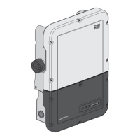
2.3.1 Symbols on the Inverter
2.3.2 Symbols on the Type Label
Symbol Explanation
Operation display.
Indicates the operation condition of the inverter.
Ground fault, varistor defective or string fuse defective
Read section 9”Troubleshooting” (page66).
Disturbance or fault
Read section 9”Troubleshooting” (page66).
Tap to switch on the display light and switch to the next display message.
Electronic Solar Switch (ESS) DC load disconnection unit
• When the Electronic Solar Switch is plugged in, the DC circuit is
closed.
• To interrupt the DC circuit and disconnect the inverter securely
under load, you have to first pull out the Electronic Solar Switch
and then remove all DC plug connectors , as described in section
7.2”Opening the Inverter” (page56).
Symbol Explanation
Beware of dangerous electrical voltage.
The inverter operates at high voltages. All work on the inverter must be
carried out by qualified personnel only.
Beware of hot surface.
The inverter can become hot during operation. Avoid contact during
operation.
Observe all documentation that accompanies the inverter.
 Loading...