4.2 Requirements for Transport and Mounting
4.2.1 Requirements and Ambient Conditions
☐ The maximum permissible gradient of the access road is 4%.
☐ During unloading, a distance of at least 2m to neighboring obstacles must be observed.
☐ The access road must be constructed to ensure that a truck (16m long, 2.70m wide, 5m high, and a total weight
of 50t) can reach the unloading site. The curve radius of the truck must be taken into account.
☐ For trucks with several containers, the access roads and the unloading site must be designed corresponding to the
length, width, height, total weight and curve radius of the truck.
☐ The unloading site for the crane and truck must be firm, dry and horizontal.
4.2.2 Center of Gravity Marker
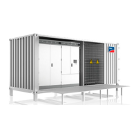
The center of gravity of the MVPowerStation is not in the middle of the unit. Take this into consideration when
transporting the MVPowerStation. The center of gravity depends on the device class of the MVPowerStation.
The center of gravity of the MVPowerStation is marked on the station container.
Figure 24: Center of gravity symbol
4.3 Transporting the MVPowerStation Using a Crane
Requirements:
☐ The crane and hoist must be suitable for the weight.
☐ The hoist must be properly connected to the crane.
☐ The factory-fitted transport lock on the devices of the MVPowerStation must be in place.
☐ The doors of the MVPowerStation must be closed.
Procedure:
1. Attach the hoist to the four upper or lower lifting lugs on the
MVPowerStation. When the hoist is attached to the lower
lifting lugs, you should protect the enclosure of the
MVPowerStation from mechanical damage by the hoist.
2. Ensure that the hoist is attached correctly.
3. Slowly raise the MVPowerStation and check if the hoist is taut evenly.
4. If the MVPowerStation is not level when raised, lower it back down to the ground.
5. Make sure that the hoist is attached so that the MVPowerStation will be lifted level. If necessary extend the
chains of the hoist with shackles, so that the MVPowerStation is in a horizontal position.
6. Raise the MVPowerStation slightly.
4 Transport and Mounting
SMA Solar Technology AG
System Manual 41MVPS22JP-SH-en-11
 Loading...

