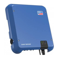
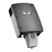
Damage to the product due to non-removal of transport lock
The product is provided with a special security lock for transport to protect it from moisture. Non-removal of the
transport lock can cause condensation and overheating during operation.
• Prior to installation work, ensure that all transport locks on the product are removed.
DC-side disconnection
The DC main distributions and DC subdistributions should be equipped with load-break switches or circuit
breakers. Load-break switches or circuit breakers enable trouble-free DC-side disconnection of the inverter.
5.2 Installation Sequence
The sequence of installation work given in this section is recommended by SMA. It is important to begin the installation
with the preparatory work and the grounding connection. Therefore, SMA recommends that you adhere to this
sequence to avoid problems during installation. Some of the installation work will only need to be carried out for
certain options.
Task See
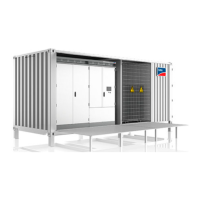
Removing the transport locks from the inverter compartment Section5.3.1, page52
Removing the desiccant bag Section5.3.5, page56
Removing the transport locks in the MV transformer compartment Section5.3.3, page54
Working in the compartment of the medium-voltage switchgear Section5.3.4, page55
Inserting the cables Section12.4, page167
Grounding the station container Section5.4, page57
Installing the AC connection
Depending on the order option, the AC connection will be installed on the
medium-voltage switchgear or the MV transformer.
Section5.5, page58
Installing the communication
Depending on the order option, the communication will be connected in the
Communit or in the inverter.
Section5.7.1, page63
Connecting the communication in the inverter with optical fibers Section5.7.2.1, page65 or
Section5.7.2.2, page67
Connecting the communication in the inverter with copper cables Section5.7.1.2, page64
Connecting the communication in the Communit with optical fibers Section5.7.1.1, page63
Connecting the communication in the Communit with copper cables Section5.7.1.2, page64
Connecting cables for analog setpoints Section5.7.2.4, page69
Connecting the external fast stop Section5.7.2.5, page69
Connecting the remote shutdown Section5.7.2.6, page70
Connecting the external insulation monitoring alert Section5.7.2.7, page70
Connecting the monitoring of the AC contactor Section5.7.2.8, page70
5 Installation
SMA Solar Technology AG
System Manual 51MVPS22JP-SH-en-11
 Loading...
