☐ SMA Solar Technology AG must have access to the safety documentation for the construction site.
☐ All system documentation such as cabling diagrams must be present.
6.3 Visual Inspection and Mechanical Test
6.3.1 Sequence for Visual Inspection and Mechanical Test
Procedure See
1. Ensure that the minimum clearances are complied with. Technical Information "Informa-
tion on Transportation and Instal-
lation of the MV Power Station"
2. Ensure that the grounding busbar has been professionally connected to
the external grounding system.
Section6.3.2.1, page74
3. Ensure that the cables for communication, control, supply voltage and
monitoring are correctly connected.
Section6.3.2.3, page75
4. Ensure that the high-current contacts made on the installation site are cor-
rectly connected.
Section6.3.2.4, page75
5. Ensure that the high-current contacts made at the factory are correctly
connected.
Section6.3.2.2, page75
6. Ensure that the connection busbars do not show any discoloration.
If the connection busbars show any discoloration, contact the Service. (see Section17 "Contact", page256
)
7. Ensure that the settings of the switching units are made correctly. Section6.3.3.1, page76
8. Ensure that all connectors are correctly connected. Section6.3.3.2, page76
6.3.2 MVPowerStation
6.3.2.1 Checking the Grounding
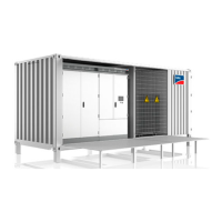
Figure 36: Grounding of the station container
Position Designation
A Grounding busbar
6 Commissioning
SMA Solar Technology AG
System ManualMVPS22JP-SH-en-1174
 Loading...
