5 Mounting the New Power Unit
Service Manual SBxx-1SP-US-40-AT-PU-SG-xx-13 11
10. If necessary, remove residual insulation material
from the two connection openings at the top of the
Connection Unit.
5 Mounting the New Power Unit
Procedure:
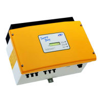
1. Disconnect the inverter from voltage sources (see inverter manual).
2. Hook the new Power Unit into the upper recesses of the wall mounting bracket, thus plugging
the Power Unit into the Connection Unit. Make sure that the screw holes on the left and right
sides of the PowerUnit are directly over those of the ConnectionUnit; and the cables
protruding from the PowerUnit must not be pinched.
3. Tighten 2 screws with 2 washers on the right and left side of the PowerUnit (TX25) (torque:
6Nm ± 0.3Nm (53in-lb ± 2.65in-lb)).
4. If the enclosure lid of the new Power Unit is a
transport lid (see information on the enclosure lid),
replace the transport lid of the new Power Unit with
the enclosure of the defective Power Unit. To do so,
loosen all screws of the upper enclosure lid (TX25)
and remove it.
5. Position the upper enclosure lid with the 6 screws
and serrated conical spring washers on the
enclosure and tighten it in the specified order (TX25,
torque: 6Nm (53in)).
6. Secure the inverter to the wall mounting bracket. To
do this, insert the screw M5x60 through the hole on
the left side of the PowerUnit and screw it into the
thread (TX25, torque: 1.7Nm ± 0.3 Nm (15.05in-
lb ± 2.65in-lb)).
ENGLISH

 Loading...