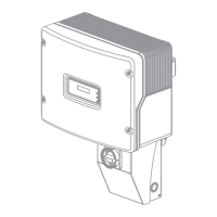
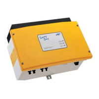
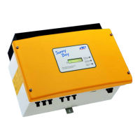
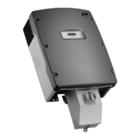
5 Mounting the New Power Unit
Service ManualSBxx-1SP-US-40-AT-PU-SG-xx-1312
7. If the inverter is to be protected against theft, attach
a padlock: To do this, guide the shackle of the
padlock through the provided hole on the left side
of the Power Unit and close the shackle. Keep the
key of the padlock in a safe place.
8. Pull the ribbon cable used to connect the
communication assembly to the PowerUnit into the
ConnectionUnit, and plug it into the jack on the
communication assembly.
COM
SPS
AC-out
D-IN
SPS
A B
M1
X1 X2
M2
ANT.
FCC ID: SVF-KP20
IC: 9440A-KP20
9. Plug the terminal block with the connected DC
conductors into slot DC-in in the Connection Unit.
While doing so, only touch the terminal block on the
black enclosure.
COM
DC-in
1
2
A+ B+ C+ A− B C−
−
A+ B+ C+ A− B− C−
10.
DANGER
Danger to life due to electric arc
The terminal block must be fastened to the slot with 2 screws. If the terminal block is not
correctly mounted and comes out of the slot, an electric arc can form. An electric arc can
cause life-threatening injuries.
• Mount the terminal block on the slot as described in the following.
11. Tighten (torque: 1.7Nm ± 0.3 Nm (15.05in-lb ±
2.65in-lb)) the screws of the terminal block using a
flat-blade screwdriver (blade width: 3.5mm).
12. Ensure that the terminal block is securely in place.
ENGLISH
 Loading...
