4 Single System SMA Solar Technology AG
18 Off-Grid-IS-en-30 Installation - Quick Reference Guide
4.2 Connecting the Sunny Island
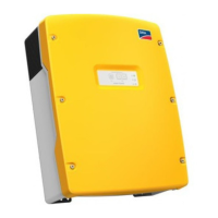
Figure6: Connecting the Sunny Island inverter
Position Designation Description/information
A AC power cable of the
stand-alone grid
Sunny Island: connection to AC1 Loads/SunnyBoys terminals L, N,
and PE
Conductor cross-section: maximum 16 mm²
B AC power cable of the
generator
Sunny Island: connection to AC2 Gen/Grid terminals L, N, and PE
Conductor cross-section: maximum 16 mm²
The Sunny Island must be connected via a grounding conductor on the
terminal AC1 or AC2 to the ground potential. The conductor cross-section
of the grounding conductor must be 10 mm² or larger. If the conductor
cross-section is smaller, an additional grounding conductor on the
enclosure with the conductor cross-section of the AC power cable must
connect the Sunny Island with the ground potential.
C DC+ cable Battery terminal
Conductor cross-section: 50 mm² to 95 mm²
Cable diameter: 14 mm to 25 mm
D DC − cable
E Control cable, generator Sunny Island: Relay1 NO and Relay1 C terminals
Conductor cross-section: 0.2 mm² to 2.5 mm²
 Loading...

