Do you have a question about the SmartLift SL 608 and is the answer not in the manual?
Components related to the vacuum system.
Components related to the power supply.
Components related to the wheels.
Components related to the 24V system.
Miscellaneous components of the machine.
Components related to the drive system.
Safety guidelines for daily use of the machine.
Safety precautions related to the vacuum system and its operation.
Safety warnings about the risk of overturning and stability.
Safety check for the lift yoke before use.
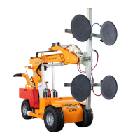
Visual overview of the SmartLift machine with labeled components.
Operation of the lifting arm's vertical movement.
Operation of the arm's tilting function.
Operation of the telescopic arm's extension and retraction.
Operation of the arm's side displacement function.
Operation and function of the emergency stop button.
Operation of the main power switch for all electric functions.
Activation and control of the drive motor.
Control for moving the machine forward and backward.
Function and effect of the safety switch.
Details on the vacuum meter and safety switch components.
Visual identification of vacuum system components located on the top of the machine.
Visual identification of vacuum system components located on the bottom of the machine.
Location and function of the emergency stop switch.
Description of the alarm light for vacuum status.
Explanation of the battery indicator and operation time display.
Description of the acoustic alarm for vacuum status.
Control for raising the lifting arm.
Control for lowering the lifting arm.
Control for tilting the arm forward.
Control for tilting the arm backward.
Control for retracting the telescopic arm.
Control for extending the telescopic arm.
Control for shifting the arm to the right.
Control for shifting the arm to the left.
Step-by-step guide on how to operate the manual extension arm.
Important safety reminder for operators when using the manual extension.
Procedure for adjusting the machine's tip head to two positions.
Operator responsibility and safety advice for adjusting the tip head function.
Notes on ensuring the yoke is correctly placed and bolts are in position.
Advice on washer placement when the yoke has been dismantled.
First steps and common checks for troubleshooting any fault on the Smartlift.
Overview of the three main categories for fault diagnosis.
Troubleshooting steps if the vacuum pump does not run.
Steps to diagnose issues when the vacuum pump runs continuously.
Diagnosing faults when the pressure gauge shows -0.7 bar or higher.
Diagnosing faults when the pressure gauge shows -0.55 bar or lower.
Diagnosing faults when the pressure gauge indication drops after disconnection.
Troubleshooting intermittent vacuum pump operation.
Diagnosing issues with intermittent pump operation and pressure drops.
Steps to take when there is no response from the control panel for all functions.
How to handle situations where the safety switch has been activated.
Visual and acoustic checks for actuator faults and line issues.
Details on the actuator responsible for tilting the yoke.
Details on the actuators responsible for lifting the arm.
Procedure to re-establish normal function when lift actuators stop due to load.
Information regarding the required annual servicing of the SL-OUTDOOR.
Identification of the controller for the tilting actuator.
Identification of the controllers for the lifting actuators.
Identification of the controller for the telescoping actuator.
Identification of the controller for the side shift actuator.
Voltage checks for lifting actuators via clamps.
Information on switching off the safety switch below lifting actuators.
Troubleshooting steps for no actuator reaction, including voltage checks.
Information on disconnecting the security switch and associated voltage checks.
Diagnosing remote control faults when moving single actuators.
Activating the control panel for tilt, side shift, or telescopic arm movement.
Troubleshooting when there is no reaction and no other faults are present.
Checks for main switch, ON/OFF switch, and battery charge for lever response.
Verifying the integrity of fuses for the drive motor and controller.
Identification and description of drive engine, electric brake, and actuator for side shift.
Details of the Victron Energy Blue Power Charger IP65.
Explanation of the LED indicators on the battery charger.
Wiring diagram for the main control box and its connections.
Wiring details for vacuum pumps, relays, and associated components.
Wiring connections for the battery and external charger.
Wiring diagram for the emergency stop and safety switch.
Specific wiring pin assignments for the engine.
Specific wiring pin assignments for the steering system.
Wiring details for the battery indicator.
Wiring details for the Curtis controller.
Wiring for the emergency stop function.
Wiring for the safety switch and audible/visual alarms.
Wiring diagram for vacuum pumps and associated relays.
Layout and wiring of components on the control panel.
| Brand | SmartLift |
|---|---|
| Model | SL 608 |
| Category | Lifting Systems |
| Language | English |