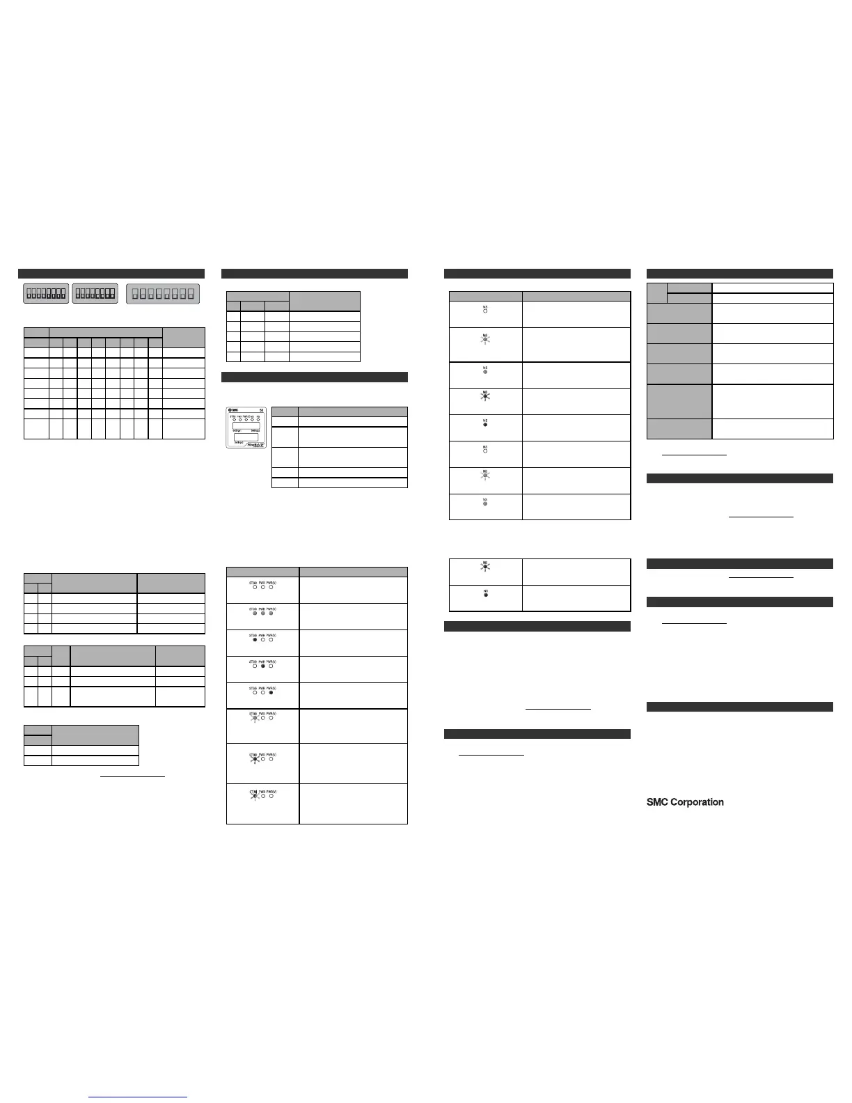
LED Display
The status display LED displays the power supply and communication
status.
Display
ST(M)
PWR
PWR(V)
MS
Content
Displays the diagnostic status of the unit.
Displays the status of the power supply
voltage for control and input.
Displays the status of the power supply
voltage for outputs.
Displays the module status.
NS Displays the network status.
•SI unit common status
Content
The power supply for control and input is
OFF.
LED display
OFF.
The unit is in normal operation.
Green LEDs are ON.
A component failure inside the SI unit.
Red ST(M) LED is ON.
The power supply voltage for control and
input is abnormal.
Red PWR LED is ON.
The power supply voltage for output is
abnormal.
Red PWR(V) LED is ON.
Troubleshooting
Refer to the LED Display. Refer to the SMC website
(URL http://www.smcworld.com) to obtain more detailed information
about troubleshooting.
Setting and Adjustment
Refer to the SMC website (URL http://www.smcworld.com) to obtain
more detailed information about setting and adjustment.
Diagnostic
Commissioning
•Parameter Setting
•Hardware Configuration (EDS file)
•I/O Map
Outline with Dimensions
Refer to the product catalogue or SMC website
(URL http://www.smcworld.com) to obtain more detailed information
about outline dimensions.
Refer to the SMC website (URL http://www.smcworld.com
) to obtain
more detailed information about diagnostics.
Refer to the SMC website (URL http://www.smcworld.com
) to obtain
more detailed information about these settings.
A unit other than the SI unit has been
detected.
Green ST(M) LED is
flashing.
Either of the following conditions:
•The valve ON/OFF counter has
exceeded the set value.
•The valve is short circuited or
disconnected.
Red ST(M) LED is flashing.
Either of the following conditions:
•Connection error between units has
occurred.
•Configuration memory error has
occurred.
Red/Green ST(M) LED is
flashing alternately.
A component failure inside the SI unit.
Red MS LED is ON.
The power supply for control and input is
OFF, or IP address is not set.
NS LED is OFF.
•EtherNet/IP
TM
status
Content
The power supply for control and input is
OFF.
LED display
MS LED is OFF.
Either of the following conditions:
•The unit has not been configured
correctly.
•Fieldbus is idling.
Green MS LED is flashing.
The unit is in normal operation.
Green MS LED is ON.
Recoverable error.
Red MS LED is flashing.
Specification
Maintenance
•Maintenance should be performed according to the Safety Instructions.
•Perform regular maintenance and inspections.
There is a risk of unexpected malfunction.
•Do not use solvents such as benzene, thinner etc. to clean each unit.
They could damage the surface of the body and erase the markings on
the body.
Use a soft cloth to remove stains.
For heavy stains, use a cloth soaked with diluted neutral detergent and
fully squeezed, then wipe up the stains again with a dry cloth.
Refer to the SMC website (URL http://www.smcworld.com
) to obtain
more detailed information about maintenance.
Contacts
AUSTRIA (43) 2262 62280 NETHERLANDS (31) 20 531 8888
BELGIUM (32) 3 355 1464 NORWAY (47) 67 12 90 20
CZECH REP. (420) 541 424 611 POLAND (48) 22 211 9600
DENMARK (45) 7025 2900 PORTUGAL (351) 21 471 1880
FINLAND (358) 207 513513 SLOVAKIA (421) 2 444 56725
FRANCE (33) 1 6476 1000 SLOVENIA (386) 73 885 412
GERMANY (49) 6103 4020 SPAIN (34) 945 184 100
GREECE (30) 210 271 7265 SWEDEN (46) 8 603 1200
HUNGARY (36) 23 511 390 SWITZERLAND (41) 52 396 3131
IRELAND (353) 1 403 9000 UNITED KINGDOM (44) 1908 563888
ITALY (39) 02 92711
URL http://www.smcworld.com (Global) http://www.smceu.com (Europe)
Specifications are subject to change without prior notice from the manufacturer.
© 2010 SMC Corporation All Rights Reserved.
LED Display (Continued)
•IP address setting switch
192.168.0.254
:
192.168.0.1
1
192.168.1.254
2
OFF
:
ON
OFF
ON
:
OFF
ON
OFF
:
OFF
ON
3
ON
:
OFF
ON
Settings2
:
192.168.1.1
DHCP mode
∗
1
Remote Control
mode
∗
2
:
ON
ON
OFF
:
OFF
ON
OFF
:
ON
ON/OFF
ON/OFF
:
OFF
ON
OFF
Settings1
8
4 5
ON
:
OFF
ON
ON
:
OFF
ON
6
ON
:
OFF
ON
:
OFF
ON
OFF
:
OFF
ON
OFF
:
OFF
ON
OFF
7 8
ON
:
OFF
ON
ON
:
OFF
ON
:
OFF
ON
OFF
:
OFF
ON
OFF
•V_SEL switch: The number of outputs (size) occupied by the SI unit is
selected.
Content
Number of valves = 32 outputs
Number of valves = 24 outputs
Number of valves = 16 outputs
Settings3
1
Number of valves = 8 outputs
SI unit output data size
4 byte (Default setting)
3 byte
2 byte
1 byte
2
OFF
OFF
ON
ON
OFF
ON
OFF
ON
•Diagnostics switch: Allocates the diagnostic data to the input data.
Content
Input data only (Default setting)
Input data + System diagnosis
Input data + System diagnosis +
Unit diagnosis (Up to 10 units)
Settings3
3
Diagnostic size set
for the input
0 byte
4 byte
6 byte
4
OFF
OFF
ON
OFF
ON
OFF
Mode
0
1
2
•EtherNet/IP
TM
communication setting switch.
Automatic
10 Mbps, half duplex
10 Mbps, full duplex
100 Mbps, half duplex
Settings3
100 Mbps, full duplex
Communication speed full
duplex/half duplex setting
6
OFF
ON
ON
ON
ON
7 8
ON/OFF
OFF
OFF
ON
ON/OFF
OFF
ON
OFF
ON ON
∗1: The mode to obtain IP address from DHCP server. Obtained IP address is
lost when the power supply is cut.
∗2: The mode to respond to the commands from the BOOTP/DHCP Server
provided by Rockwell Automation.
Enable DHCP: IP address etc. can be obtained from BOOTP/DHCP Server.
If the power is supplied again in this state, information
including IP address is obtained again.
Disable DHCP: IP address etc. cannot be obtained from BOOTP/DHCP
Server.
If the power is supplied again with this condition, previous
setting can be held.
•HOLD/CLEAR switch: Sets the output status when the fieldbus has a
communication error or is in idling.
Content
Output is OFF. (Default setting)
Holds the output.
Settings3
5
OFF
ON
IP address
Setting and Adjustment (Continued)
Connection timeout.
Red NS LED is flashing.
IP address is duplicated.
Red NS LED is ON.
The unit received an IP address, but
connection is not established.
Green NS LED is flashing.
Connection is established.
Green NS LED is ON.
EX600-TFN25
-10 to 50
o
C
(Max. surrounding air temperature rating: 50
o
C)
Connected load
-20 to 60
o
C
Operating temperature
range
For use in Pollution Degree 2 Environment
(UL508)
Pollution degree
24 VDC 1.5 W (SMC)
Solenoid valve with LED and circuit protection
10 to 57 Hz: constant amplitude 0.75 mm p-p
57 to 150 Hz: constant acceleration 49 m/s
2
for 2 hours each in direction X, Y and Z
respectively (De-energized)
Vibration resistance
147 m/s
2
3 times each in directions of X, Y and
Z respectively (De-energized)
Impact resistance
24 VDC Class2, 2 A
Power
supply
24 VDC Class2, 2 AOutput
Control and input
Storage temperature
range
Refer to the product catalogue or SMC website
(URL http://www.smcworld.com) to obtain more detailed information
about product specifications.
 Loading...