- 5 -
4. Replacement parts list
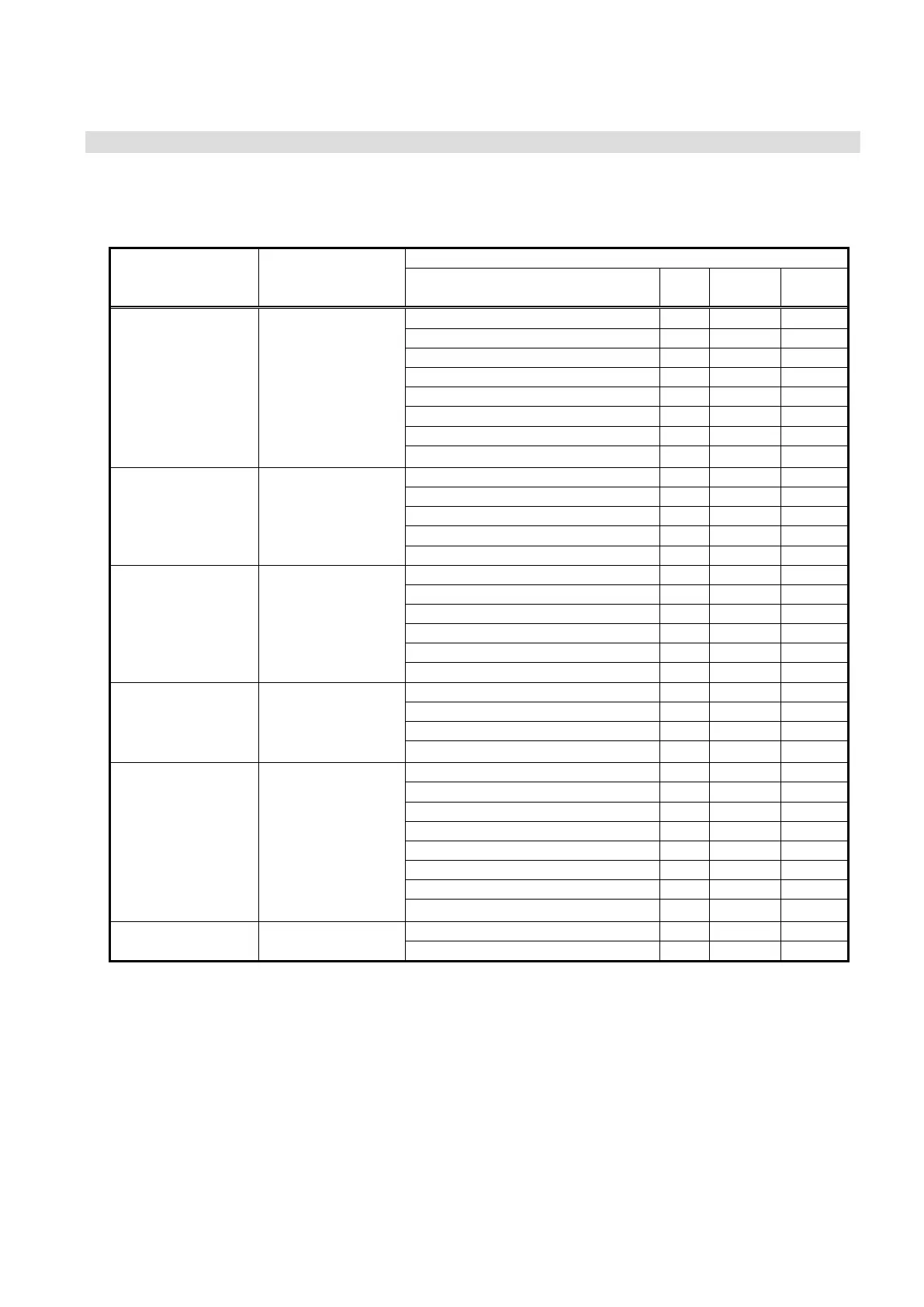
The replacement parts can be ordered with the following part numbers.
Each set includes the components shown on the right of this table. Refer to the drawing number and item
number in this manual to check each part.
Component
Part number Description
Description Qty.
Drawing
No.
Item
No.
Piston seal 2 Fig. 1 (5)
Rod seal 1 Fig. 2 (14)
Governor gasket 2 Fig. 1 (2)
Valve assembly 1 Fig. 3 (3)
Governor chamber assembly 1 Fig. 3 (4)
Check valve 4 Fig. 2 (5)
Valve spring 1 Fig. 3 (2)
KT-VBA10A-1
Booster regulator
maintenance
parts set
Grease package 1
- -
Switch valve assembly 1 Fig. 2 (9)
Exhaust sleeve 2 Fig. 2 (10)
Travel spring 1 Fig. 2 (11)
Push rod 2 Fig. 2 (12)
KT-VBA10A-2 Switch valve set
O-ring 2 Fig. 2 (13)
Governor chamber assembly 1 Fig. 3 (4)
Valve assembly 1 Fig. 3 (3)
Valve spring 1 Fig. 3 (2)
Regulating piston assembly 1 Fig. 3 (7)
Relief valve 1 Fig. 3 (5)
KT-VBA10A-3
Governor
chamber set
Relief spring 1 Fig. 3 (6)
Piston seal 2 Fig. 1 (5)
Rod seal 1 Fig. 2 (14)
Governor gasket 2 Fig. 1 (2)
KT-VBA10A-4 Seal kit
Grease package 1
- -
Check valve 4 Fig. 2 (5)
Check valve spring 4 Fig. 2 (6)
Plunger 2 Fig. 2 (7)
Side plate insert A 1 Fig. 2 (3)
Side plate insert B 1 Fig. 2 (4)
Side plate gasket A 2 Fig. 2 (15)
Side plate gasket B 2 Fig. 2 (16)
KT-VBA10A-5 Check valve set
Grease package 1
- -
Bonnet 1 Fig. 3 (10)
KT-VBA10A-6 Bonnet set
Handle 1 Fig. 3 (11)

 Loading...


