BMD-20DIN
DC brush motor controller
User manual
Tallinn Science Park Tehnopol, Akadeemia tee 21/6,
Tallinn 12618, Estonia
Phone: + 372 6559914,
e-mail: sale@smd.ee
url: http://smd.ee
In case of short-circuit of motor phases or overcurrent 30A for 15 µs, the controller turns to an
emergency mode, deenergizes the motor and indicates the alarm by LED blinking.
In case of motor current exceeds the set limit for 5 sec, the controller also turns to an emergency
mode, Red LED is blinking.
To reset the emergency mode, reset the power supply of the controller.
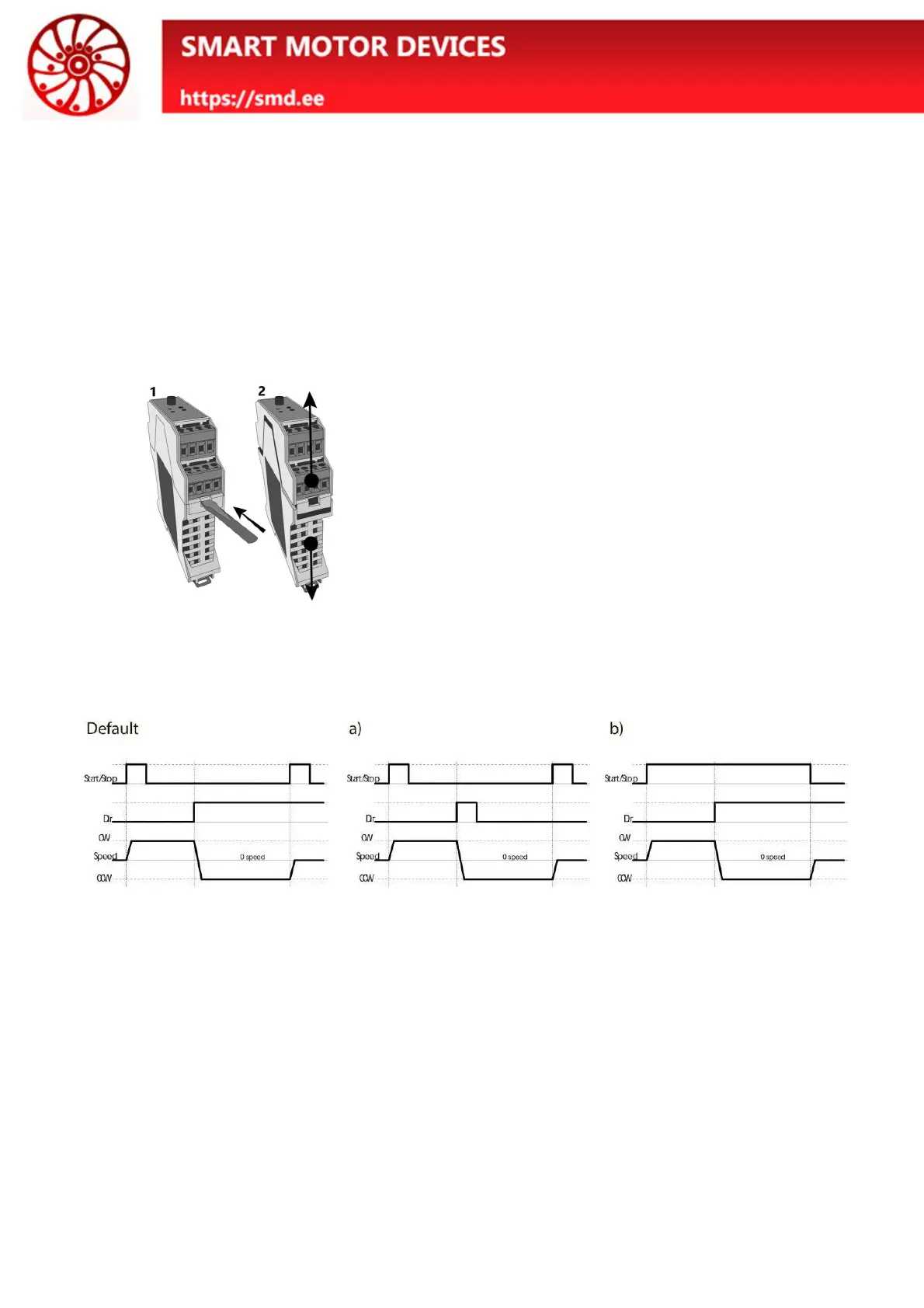
7. Input signals logic
The controller BMD-20DIN provides few options for processing of input signals START/STOP and
DIR. Jumpers for selection of the necessary options are located on the electronic board under the case of the
controller.
Fig. 4. Take off the case
To open the case:
· Turn off the power supply.
· Disconnect the terminals from the controller;
· Remove the controller from the DIN rail;
· Open the controller case as shown in the fig.
4:
1. Press down on the latch with a flathead
screwdriver on both sides;
2. Pull the top and bottom of the case
apart;
· Set the jumpers to the required position
As a default the controller is supplied with standard signal logic: input START/STOP is processed as
per the front edge of the signal, input DIR is processed as per the signal level.
Operation logic of the inputs "START/STOP" and "DIR" can be adjusted with the jumpers
"START_PIN" and "DIR_PIN" – fig. 5.
If the corresponding pair of contacts is closed by a jumper, their state corresponds to the “ON” value.
If the jumper doesn’t close the contacts, the state of the contacts corresponds to the value "OFF".
 Loading...