Technical specification
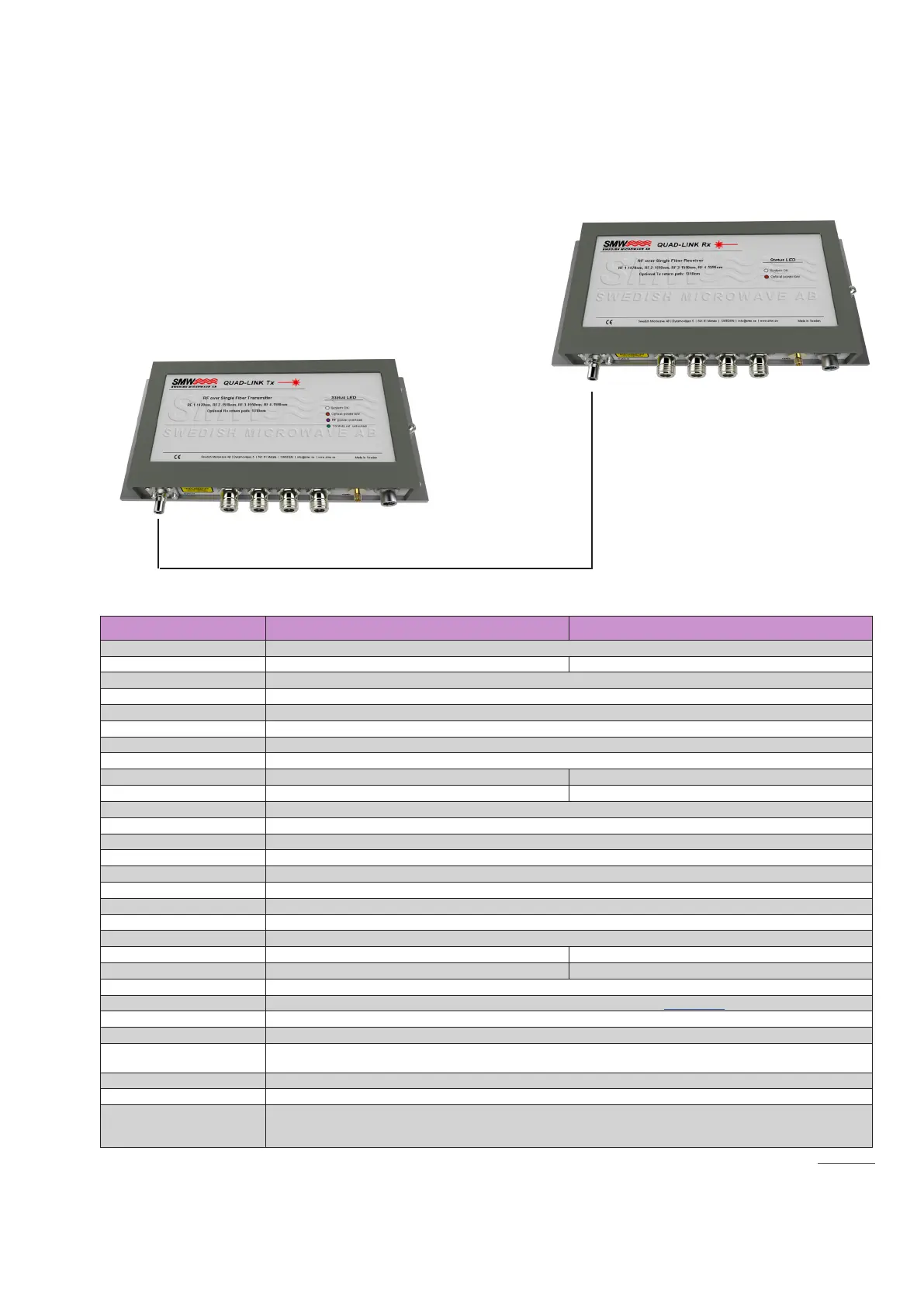
Four channel RF over Fiber
Transmitter / Receiver System
8
TECHNICAL SPECIFICATIONS
MODEL: Quad-Link Fiber Transmitter Quad-Link Fiber Receiver
RF Frequency 290 - 3000 MHz (50 - 2750 MHz as option, w/o 10 MHz ref.)
Input Level RF / Fiber -10 to -50 dBm @ 20 transponders -6 dBm to +5 dBm
Optical Output / Input Direct modulated DFB lasers, CWDM wavelenghts: CH1 1470 nm, CH2 1510 nm, CH3 1550 nm, CH4 1590 nm
Optical Output Power 8 mW ( 2 mW / channel )
Return Channel Wavelength 1310 nm
System Gain Variation ± 0.20 dB within 30 MHz, ± 1 dB @ 950 - 2150 MHz, ± 2 dB @ 290 - 3000 MHz, ± 3 dB @ 50-2750 MHz max.
System Noise Figure 15 dB typ.
10 MHz Phase Noise -123 dBc@100 Hz, -140 dBc@1kHz, -150 dBc@10kHz, -155 dBc@100 kHz
10 MHz Ref. Output / Input Level 0 dBm on all RF ports and separate output port. -10 to + 5 dBm input via separate 10 MHz connector.
IP3 RF Input / IP3 RF output +25 dBm typ. +30 dBm typ.
RF Return Loss / VSWR N / SMA connector: min. 12 dB / 1.7:1, F connector: min. 8 dB / 2.3:1
System C/N, Single carrier > 56 dB @ 30 MHz
System C/N, 40 transponders > 33 dB @ input level -15 dBm (composite level)
SFDR 115 dB/Hz
Fiber Connector Dual ber, Single mode Huber & Suhner, Q-ODC
RF Connectors F-type 75Ω / N-type 50Ω / SMA-type 50Ω
Separate10 MHz Connector F-type 75Ω / N-type 50Ω / SMA-type 50Ω
DC Connector Fischer ® 103 series, Circular IP 68 sealed
DC Input +12 to +28 V
DC LNB Supply 600 mA max. / RF port, Autofused, Shortcircuit protected
Power Consumption 6 W max. (excl. 600mA / RF Port for LNB Powering) 5 W max.
Temperature Range - 40° to + 80° C
Dimensions 273 (L) x 154.4 (W) x 34.4 (H) mm, for drawing, see www.smw.se
Weight 1890 g (SMA- & F-connectors), 1950 g (N-connectors)
Ingress Protection Code IP 67, Q-ODC connector only IP67 when mated with dust cover or Q-ODC cable connector
Standards Compliance
Optical interface: EIA/TIA 568, ITU std. G694.2; EMC: EN 55013:2013, EN 55020, EN 300 386; Safety: EN 60950-1, EN
60950-22, EN 60065:2002
Options AGC off (Beacon), DC connector type, 10 MHz connector type, No LNB DC supply, 50 - 2750 MHz RF freq. range
Miscellaneous Enclosed DC cable 15 meters with connector.
Accessories
Outdoor to Outdoor ber cables ( Q-ODC to Q-ODC ), Outdoor to indoor patch cables
(different connector type and lengths),
External 10 MHz ref. oscillator, Dual DC Inserter, Power Supply Unit (AC to DC), Custom DC cable length.
Rev.09-20-3C
The RF output level from the optical receiver depends on two things with a QuadLink system (with AGC):
1. Optical attenuation between optical transmitter and receiver.
2. Input level on the optical transmitter
The formulas are: Rx channel power = -6dBm - (2*optical_attenuation) - (log10(number of channels)*10)
If the RF input level is less than -15 dBm on the optical transmitter(sum of all carriers power):
Rx channel power = Tx_input_level +9 - (2*optical_attenuation) - (log10(number of channels)*10)
 Loading...