124
M4x10 (4x)
iii-4
iii-5
1
2
Installation Instructions
Fitting and connecting the monitor
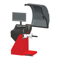
Fig. iii-4 Fitting the monitor
The 4 screws needed (M4x10) to fi x the VESA support
to the monitor are part of the kit supplied.
Fig. iii-5 Connection of monitor and PC
Caution
Before connecting the electronic cables turn off the
mains switch.
• In
sert the monitor connector into the right-hand
socket (item 1) of the embedded unit.
• Insert the monitor main connector into the socket
(item 2).
iv Test procedures
• Bal
ance a wheel to less than 0.25 oz. (5 grams) per
plane.
• Perform a User Calibration. See Chapter 6.3.1.
v Instructing the operator
(Following applies only if a unit is installed by a service
Technician)
• Show and explain the Safety Booklet.
• Show the operator how to switch the unit on and
off.
• Show the operator how to perform an emergency
stop.
• Show the operator how to select a wheel type, enter
data and apply a weight.
 Loading...