Do you have a question about the socomec DIRIS Digiware I-35 and is the answer not in the manual?
Describes electrical and fire hazards, emphasizing safety precautions.
Outlines critical checks and precautions to prevent device malfunction or damage.
Details the electrical parameters measured by different DIRIS Digiware models, including voltage, current, and power quality.
Provides crucial safety recommendations and references the hazards section prior to installation.
Explains the general procedures for mounting DIRIS Digiware modules.
Details the DIN rail mounting methods for DIRIS Digiware I-4x modules.
Details the backplate mounting methods for DIRIS Digiware I-4x modules.
Provides essential guidelines and diagrams for connecting DIRIS Digiware modules.
Explains how to connect the various types of current sensors.
Outlines the general concept for connecting current sensors to DIRIS Digiware.
Provides specific RJ12 connection details for TE, TR, and TF sensors.
Details how to connect the system to electrical networks and loads.
Describes common network and load connection combinations.
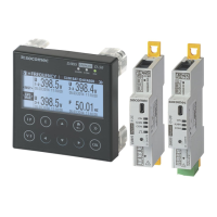
Explains the fundamental principle and components of the Digiware Bus system.
Details how to calculate and select the appropriate power supply for the system.
Provides a table listing the power consumption of various system components.
Outlines the rules and examples for determining the maximum number of devices on the Digiware BUS.
Explains the requirement and function of the Digiware Bus repeater.
Explains the system's auto-addressing feature for automatic device addressing.
Sets out essential rules for connecting DIRIS Digiware via RS485 and the Digiware bus.
Explains how to configure the system using the Easy Config software.
Describes various connection modes for using Easy Config with DIRIS Digiware.
Guides users through the steps involved in configuring devices with Easy Config.
Details how to synchronize device times using NTP or manually.
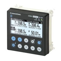
Explains how to configure the system directly from the DIRIS Digiware D remote display.
Describes the connection mode for configuring via the remote display.
Explains how alarms are generated based on various events and parameter thresholds.
Details alarms configured based on electrical measurements like voltage, current, and power factor.
Explains system alarms triggered by installation errors.
Details the performance classes of DIRIS Digiware with associated sensors as per IEC 61557-12.
| Brand | socomec |
|---|---|
| Model | DIRIS Digiware I-35 |
| Category | Measuring Instruments |
| Language | English |