Do you have a question about the Sokkia GRX3 and is the answer not in the manual?
Product is designed for professional use with good knowledge of safe operation.
Information is intellectual property of TPS; all rights reserved.
Lists Sokkia and other product/company trademarks.
States the product is provided "AS-IS" and limits liability.
Outlines terms for using supplied software with the receiver.
Statements on TPS website and literature do not modify terms.
Information on downloading manuals, software from Sokkia Care.
Improper use can lead to injury or malfunction; repair by authorized centers.
Terms and conditions governed by California law.
Explains conventions like Bold, Mono, Italic used in the manual.
Further information for system configuration, maintenance, or setup.
Supplementary info affecting operation, performance, or data integrity.
Notification of potential minor injury, damage, or warranty loss.
Notification of potential personal injury or property damage.
Notification of potential severe personal injury or death.
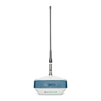
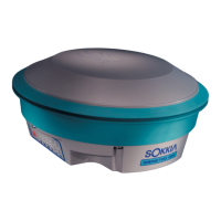
Overview of GRX3 as a compact, high-performing GNSS receiver.
Mentions advanced features like multi-path mitigation, TILT, HIMU, IP67.
Lists key features like 226 GNSS channels, Fence Antenna, internal battery.
Lists available configurations like no cellular, UHF radio, cellular module.
Lists items included in the standard GRX3 kit.
Mentions Sokkia offers various accessories for flexibility and efficiency.
This document provides detailed usage information.
Provides basic hardware, LED, safety, and regulatory info.
On-screen help for SRU software details.
Software for configuring/updating GNSS receivers and peripherals.
Mentions MAGNET Field, GeoPro, Pocket 3D for data collection/analysis.
Suggests checking troubleshooting section for solutions.
Advise contacting dealer or Sokkia Care for assistance.
Details information needed for better technical assistance.
Steps to save receiver information via SRU to a file.
Details specs of devices/software needed for problem reproduction.
Information about system software version and reproduction steps.
Description of field environment and observation conditions.
Provides current product info, manuals, FAQs.
Support for registered users, training, updates, troubleshooting.
Lists five configurations of the GRX3 receiver.
Identifies reset button, SIM card door, external GNSS connector.
Shows GRX3 components for this configuration.
Shows GRX3 components for this configuration.
Panel shows operational status; see Display Panel chapter for details.
Door location, removal, and reset button access.
GSM functionality enabled by Micro-SIM; cellular operation based on services.
Steps to reset the receiver using the hardware button.
Hardware reset does not erase TPS data files or user settings.
Labels on bottom include serial and part numbers.
Lists power supply, USB, and power adapter cables.
Note on aligning keyways for power/serial cable connection.
Lists optional cables like Alligator Clips, SAE extension, External Antenna.
Lists accessories for flexibility and efficiency like power supply, antennas, tribrachs.
Receiver has an internal, non-removable, rechargeable battery with two cells.
BNC connector for UHF modem antenna on the radome.
Details power, serial, and micro-USB ports on the bottom.
GNSS and Cellular antenna connectors on the bottom.
Panel for control/viewing status, data logging.
Describes functions based on press duration, LED indicators.
Details power off, logging, reset functions via power button.
Explains the LED display panel and its icon key.
Details status LED colors and behavior for tracking satellites.
Explains LED indications for file logging, deletion, formatting.
Describes LED status for Bluetooth activity and connections.
Details LED colors and patterns for the cellular module.
Explains LED colors/patterns for the UHF modem.
Details LED states for command, receiver, transmitter modes.
Explains LED status for internal battery charge and charging.
Details LED states when receiver is off and power source status.
Steps to turn on the receiver using the power button.
Steps to turn off the receiver, preventing accidental shutdown.
Receiver powered by internal battery or external source (9-27 VDC).
Lists operating hours under various use conditions with internal battery.
Steps to charge the internal battery using supplied cables.
Recommended and acceptable temperatures for charging.
Receiver can survey while charging without performance degradation.
Steps to connect receiver to an external 12-volt battery.
What happens when power is insufficient and how to restore it.
Instructions for downloading and installing SRU software.
Note on uninstalling SRU via Windows Programs.
USB connection, Micro-USB cable, drivers, and firmware files.
Identifying the virtual COM port in Device Manager.
Steps in SRU to set firmware loading mode and connect.
Selecting the correct COM port for USB communication.
Steps to select target receiver and proceed with loading.
Browsing and selecting the firmware file (*.tfi).
Shows firmware upload progress.
Warning dialog upon completion of firmware upload.
Final steps and rebooting process.
Alternative method using MAGNET Field software.
OAF enables purchased options for receiver customization.
Lists examples of available upgrade options like signal tracking, RTK.
Steps to connect to SRU and check current options.
Window to view current authorization options and upload new ones.
How to get OAF files and contact Sokkia for inquiries.
Steps to right-click and select upload OAF.
Navigating to and opening the OAF file in SRU.
Clicking upload and confirming the reset.
Checking expiration date for universal OAFs and customer OAFs.
Right-clicking to view detailed OAF information.
Clears NVRAM, restores factory defaults to resolve issues.
Steps to perform a factory reset using SRU software.
Accessing the Factory Reset option in SRU Tools.
Confirmation prompt for resetting the receiver.
Steps to perform reset using the LED display.
Uses HIMU module for tilt angles to calculate true ground point coordinates.
How MAGNET Field uses tilt angle for coordinate calculation.
Automatic point measurement when pole tilt is low.
Displays bubble level and magnetic field values in field software.
Calibrates HIMU for azimuth data using e-compass.
Lists electronic level and magnetic compass calibration steps.
General recommendations for performing ELC calibration.
Steps for setting up receiver on tripod for level calibration.
Instructions for initiating and completing level calibration in software.
Steps to calibrate compass in 3D for accurate readings.
How SRU/MAGNET Field indicates calibration status.
Setup for calibrating compass in the horizontal plane.
Steps to turn receiver clockwise for calibration.
Notes on calibration completion and saving.
Conditions requiring compass recalibration.
Installing a heavy-duty tripod over a known point.
Positioning base receiver over a point with known coordinates.
Attaching antenna, leveling tripod, measuring height.
Configuring base receiver parameters in MAGNET Field.
Steps to start the receiver transmitting correction data.
Attaching receiver to pole and measuring height if needed.
Attaching antenna and inserting SIM card if applicable.
Configuring rover parameters in MAGNET Field.
Configuring cellular module for correction data and internet.
Connecting to remote server for correction data.
GRX3 designed for Sokkia active external antennas; avoid passive ones.
Steps to configure external antenna in MAGNET Field.
Steps to configure external antenna in SRU.
Determining coordinates of station marker by measuring antenna height.
How to orient receiver and measure vertical or slant height.
Diagram showing measurement points like ARP and SHMM.
Internal 8 GB memory card, FAT32 format.
Using SRU or MAGNET Field to set logging parameters.
Memory usage depends on logging rate.
Logging GNSS Raw data to memory card.
Steps to start recording using the LED display.
Steps to stop recording using the Power button.
Steps to start recording using SRU software.
Using File Explorer to manage log files.
Specifying settings like Elevation Mask, Prefix, Rotation Period.
Using MINTER to start logging one or more files.
Steps to start logging with default settings.
Steps to start logging with manual settings.
"".tps"" data files stored on FAT32 system, up to 4000 files.
Options for simultaneous files, rotation mode, auto-upload.
Upload/download files via USB connection.
How the GRX3 appears in Windows Explorer.
States where SRU cannot access storage or update firmware.
Error when file system is not mounted.
Error message for insufficient flash memory for firmware update.
Procedures to safely eject USB drive from Windows taskbar.
Procedures to safely eject USB drive from File Explorer.
Steps to mount internal memory in SRU File Explorer.
Opening the Logs tab after mounting memory.
Right-clicking files to open context menu and select Download.
Selecting the folder to save downloaded files.
Window showing download progress.
Steps to delete raw data files from receiver memory.
Checks before contacting dealer/support: connections, battery, software.
Actions to try if problems persist: power cycle, factory reset.
Possible causes and solutions when receiver fails to power on.
Cable and generic problems for connection failure.
Issues with satellite lock, options disabled/expired.
Causes for tracking few satellites, e.g., obstructions, masks.
Problems with base coordinates, options, satellite geometry.
High PDOP/GDOP values and elevation mask settings.
Issues related to modem battery status.
Problems with incompatible baud rates between modems.
Configuring radio link parameters and distance issues.
Sources of interference and how to mitigate them.
Issues with memory disabled/expired or full.
Troubleshooting steps for receiver not found by SRU.
Troubleshooting COM port access denied errors.
Reasons why no devices are discovered via Bluetooth.
Troubleshooting connection issues between SRU and receiver.
Error message for insufficient flash memory for firmware update.
How to clean and store the receiver properly.
How to contact dealer or Sokkia Care for further assistance.
Enclosure, color, dimensions, weight, antennas, battery, seals, key, LEDs.
Ports, operating/storage temp, humidity, ingress protection, vibration, drop.
Battery capacity, operating time, external power connector.
Channels, tracked signals, tracking features, data formats.
Data logging, memory capacity, ports, Bluetooth, SiteComm, serial specs.
DGPS, RTK correction formats, modes, accuracy.
Positional accuracy for various modes, start times.
Lists modem specs like frequency, spacing, modulation, protocols.
Recommendations for FEC, RSSI, channel selection, avoiding interference.
Range, type, service classes, supported profiles, frequency code.
Radio (Modem) RF and Cellular Module RF connector details.
Description and diagram of the power connector.
Description and pinout of the serial RS-232 connector.
Description and pinout of the micro-USB connector.
Table of configurations and corresponding part numbers.
Maintain distance from radio modem for RF exposure compliance.
Guidelines for correct usage and prohibited uses.
Warning about using receivers in dangerous environments.
Warnings against opening, disassembling, or modifying the battery.
Warnings against tampering and charging in incorrect conditions.
Warnings about product handling, potential overheating, and periodic testing.
Complies with FCC limits for uncontrolled equipment and RF energy.
Compliance with Class A digital device limits for interference protection.
Measures to correct radio/TV interference.
Compliance with Canadian ICES-003 and RSS standards.
Compliance with RE-D and EMC directives, CE mark.
Operating UHF radio modem only at specific frequencies with permission.
Declaration of conformity for radio performance, EMC, safety.
Declarations in various languages confirming compliance.
Product disposal as per EU waste regulations.
Compliance with Japan Radio Law for Bluetooth module.
Compliance with Bluetooth core spec profiles (Baseband, HCI, Link Manager, Radio).
Guarantee against material/workmanship defects under normal use.
Details on repair/replacement, excluded damage, remedy.
Definitions of terms like BDS, Base Station, BeiDou, Bluetooth, Ephemeris, Galileo, GNSS.
Definitions of terms like GLONASS, GPS, LEDs, MAGNET Field, MINTER.
| Type | GNSS Receiver |
|---|---|
| Static Accuracy (Horizontal) | 3 mm + 0.5 ppm RMS |
| Static Accuracy (Vertical) | 5 mm + 0.5 ppm RMS |
| Operating Temperature | -40°C to +65°C |
| Waterproof/Dustproof | Yes |
| Ingress Protection | IP67 |
| Internal Memory | 8 GB |
| Data Update Rate | Up to 20 Hz |
| Constellations | GPS, GLONASS, BeiDou, Galileo |
| RTK Accuracy (Vertical) | 15 mm + 1 ppm |
| Communication Interfaces | Bluetooth, USB, Serial |
| Battery Life | Up to 12 hours |