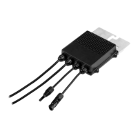
Connect the Plus (+) output connector of the module to the Plus (+) input
connector of the Power Optimiser.
Connect the Minus (-) output connector of the module to the Minus (-) input
connector of the Power Optimiser.
Figure 3: S-Series (left) and P-Series (right) Power Optimiser connectors
Step 3: Connecting Power Optimizers in Strings
You can construct parallel strings of unequal length, that is, the number
of power optimizers in each string does not have to be the same. The
minimum and maximum string lengths are specified in the power
optimiser datasheets. Refer to the Designer for string length verification.
1. Connect the Minus (-) output connector of the string’s first power optimiser to the
Plus (+) output connector of the string’s second power optimizer. When connecting
S-Series Power Optimisers, be sure to connect the short Minus (-) output connector
of one Power Optimiser to the long Plus (+) output connector of the next Power
Optimiser.
2.
To minimize electromagnetic interference (EMI), make sure to minimize the distance
between the positive and negative DC cables.
For detailed instructions, see:
https://www.solaredge.com/sites/default/files/se-emi-
performance-application-note.pdf.
3.
Connect the rest of the power optimisers in the string in the same manner.
WARNING!
If using a dual-input power optimiser and some inputs are not used, seal the
unused input connectors with the supplied pair of seals.
Chapter 2: Installing the Power Optimisers 19
Single Phase Energy Hub Inverter MAN-01-00812-1.1
 Loading...