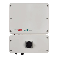
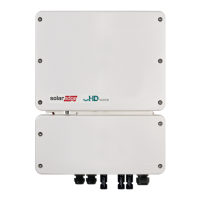
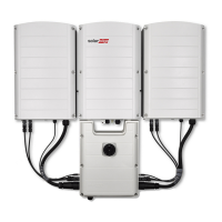
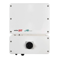
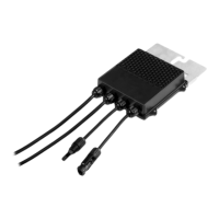
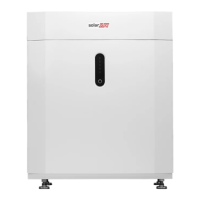
When installing a battery, connect the DC cables from the battery and from Power
Optimisers to an external combiner box, compliant with local regulation. Then, connect
the cables from the combiner box to the DCterminals inside the inverter's Connection
Unit.We recommend using the SolarEdge combiner box. For installation and
connection instructions see: https://www.solaredge.com/sites/default/files/se-
combiner-box-installation-guide-aus.pdf
NOTE
Functional electrical earthing of DC-side negative or positive poles is prohibited
because the inverter has no transformer. Grounding (earth ground) of module
frames and mounting equipment of the PV array modules is acceptable.
NOTE
SolarEdge’s fixed input voltage architecture enables the parallel strings to be of
different lengths. Therefore, they do not need to have the same number of
power optimizers, as long as the length of each string is within the permitted
range.
To connect to DCstrings:
1.
Strip 8 mm of the DC wires insulation.
2. Pass the DCwires through the DC conduit.
3.
Connect the wires to the DCterminals as shown below. Observe the correct polarity
as labeled on the terminals.
Figure 13: Inverter DC Connections
Chapter 5: Connecting the Inverter 33
Single Phase Energy Hub Inverter MAN-01-00812-1.1
 Loading...

