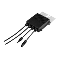
Figure 18: Single battery module connections.
1
CAN-bus (RJ45)
connectionto
invertercommunication
5 Circuit breaker, 120A
2 Groundingterminals 6
RJ45 communication socket to connect between
battery modules. NOT TO BE USED to inverter
communication.
3 DC bat - connectors 7
RS485 Communication socket to connect the
battery module below to this battery module (in
a battery tower)
4 DC bat + connector
9.
Using the power button (soft switch), turn on the battery modules, refer to
Powering
on the Battery Module
on page 29. Press the power button (soft switch) shown on
the figure below for 3-6 seconds, the LEDs will light. If this is a new battery (e.g. not
RMA) only the first green LED or the first and second green LED should light
constantly. No other LEDs should light. If you observe a different LEDs sequence,
25
Home Battery 48V Installation Guide MAN-01-00954-1.1
 Loading...