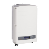
ON/OFF switch: Turning this switch ON starts the operation of the power optimizers, enables power
production and allows the inverter to begin exporting power to the utility grid. Turning it OFF
reduces the power optimizer voltage to a low safety voltage and inhibits exportation of power.
When this switch is OFF, the inverter control circuitry remains powered up.
LCD light button: Pressing this button lights up the LCD for 30 seconds. In addition, you can press this
button to access configuration menu options, as described on page 31.
Two communication glands, for connection of inverter communication options. Each gland has three
openings. Refer to Chapter 6: Setting Up Communication on page 41 for more information.
Mounting the Inverter
1 Determine the inverter mounting location, on a wall or pole, as follows:
To allow proper heat dissipation, maintain the following minimum clearance areas between the
inverter and other objects:
8" / 20 cm to the top and bottom of the inverter
4" / 10 cm to the right and left of the inverter
When installing inverters side by side, leave at least 16" / 40 cm between inverters
When installing inverters one above of the other, leave at least 16" / 40 cm between inverters.
Position the mounting bracket against the wall/pole and mark the drilling hole locations (refer to
Inverter and Mounting Bracket Dimensions on page 63):
Ensure that the U-shaped indentations are facing up and the “UP” marking is correctly oriented,
as shown below:
Figure 5: Brackets with U-shaped Indentations Facing Up
Use at least two bracket holes. Additional holes can be used to fix the bracket. Determine
which and how many holes to use according to mounting surface type and material.

 Loading...