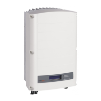
When the inverter starts converting power after the initial connection to the AC, the inverter
enters Standby mode until its working voltage is reached. This mode is indicated by the
flickering green inverter LED.
While the inverter is in Standby mode, it monitors the grid and verifies correct grid voltage and
frequency. The following message is displayed:
W a k i n g U p . . .
R e m a i n i n g : 0 5 1 S e c
The countdown indicates the seconds remaining until Production mode is entered. This time is
in accordance with local regulations and is typically between three to five minutes.
When countdown is complete, the inverter enters Production mode and produces power. This
mode is indicated by the steadily lit green inverter LED.
Step 3, Verifying Proper Operation
After the wake-up time is over, a status screen similar to the following appears on the inverter LCD panel:
V a c [ v ] V d c [ v ] P a c [ w ]
2 4 0 . 7 3 7 1 . 9 2 3 4 9 . 3
P _ O K : X X X / Y Y Y < S _ O K >
ON
1 Verify the following:
The green inverter LED is steadily lit.
The ON/OFF indicator on the LCD panel reads ON.
P_OK: XXX/YYY: There is a connection to the power optimizers and at least one power
optimizer is sending monitoring data. Optimizers send telemetries in a frequency of up to 10
minutes. Initially after pairing, both XXX and YYY values show 000 and the values increase as
paired power optimizers are reported.
S_OK appears, if the inverter is connected to the SolarEdge monitoring portal.
Vac [V] specifies the measured grid AC output voltage.
Vdc [V] specifies the DC input voltage, which should be between 250V and 450V in single phase
inverter, or between 550V and 950V in three phase inverters.
Pac [W] specifies the total AC output power produced.
2 Take note of the serial # on the inverter label. This information is used in the SolarEdge monitoring
portal to identify this inverter and is needed to open a new site in the monitoring portal.
Your SolarEdge power harvesting system is now operational.

 Loading...