4. Installation
4. Installation
15
14
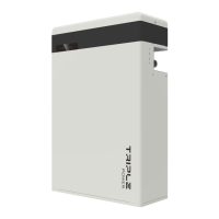
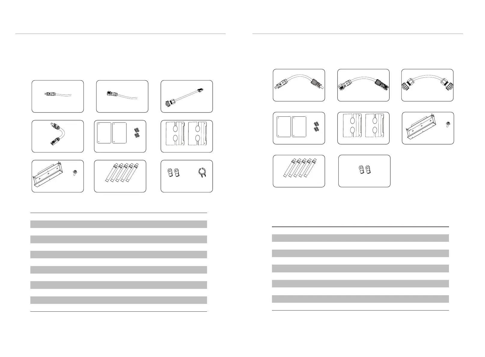
4.4.3 Accessories
E
H
J
The table below lists the number of each component.
T-BAT H 5.8:
K
Object
A
B
C
D
E
F
G
H
I
J
K
L
Description
Power cable between inverter and T-BAT H 5.8 (+) (2m)
Power cable between inverter and T-BAT H 5.8 (-) (2m)
CAN communication cable (2m)
Series-connected plug
Cover plate1
M4 screw
Cover plate2
Wall bracket
M5 screw
Expansion bolt
Ring terminal (for grounding)
Power cable disassembling tool
Quantity
1
1
1
1
2
8
2
1
1
5
2
1
L
HV11550:
Quantity Object
A1
B1
C1
D1
E1
F1
G1
H1
I1
J1
Description
Power cable between battery packs (650mm)
Power cable’ between battery packs (650mm)
RS485 communication cable (650mm)
Cover plate1
M4 screw
Cover plate2
Wall bracket
M5 screw
Expansion bolt
Ring terminal (for grounding)
A
B C
D
A1
F
I
B1
C1
G1 H1F1
I1
D1 E1
1
1
1
2
8
2
1
1
5
2
The table below lists the number of each component.
G
J1
 Loading...