74
Electrical Connection
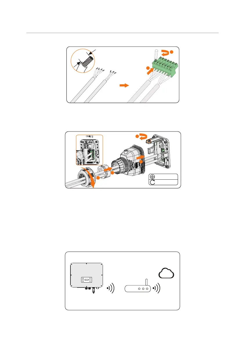
1
6 mm
Four-core
Three-core
2
Figure 8-59 Connecting to 7-pin terminal block
Step 5: Connect the assembled communication cable into the COM 2 terminal. Lightly
pull the cable to confirm tight insertion and then install the connector back.
M3
0.4 ± 0.1 N·m
1
2
4
3
Figure 8-60 Connecting to the inverter
8.8 Monitoring Connection
The inverter provides a DONGLE terminal, which can transmit data of the inverter to the
monitoring website via WiFi+LAN dongle. The WiFi+LAN dongle is equipped with 2 kinds of
communication modes (Wi-Fi mode or LAN mode).
Monitoring connection diagram
S TAT
Router
SolaX Cloud
Figure 8-61 Wi-Fi mode connection diagram

 Loading...


