Features:
KKTCC02A-A/0-20151231
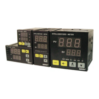
TC Series
2
3
Intellegient Temperature Controller
User Manual
Various of TC/RTD signal type are supported
⊙
⊙
⊙
⊙
Using fuzzy PID control algorithm and auto-tuning
without overshoot impulse
Different control modes for selection, kindly refer to
OT parameter for details
Switch RUN/STOP function with one key
The instruction explain instrument settings,
connections,name and etc,please read carefully
before you use the temperature controller. Please
keep it properly for necessary reference.
Model Illustration
TC 6 R 2
D
4: 48W*48H*100L 6:48W*96H*100L 7:72W*72H*100L
8:96W*48H*100L 9:96W*96H*100L(mm)
D: Version
TC Series Temperature Controller
R: relay output Q: SSR output M: relay and SSR output
K: SCR output (need to be ordered)
1: one alarm 2: 2 alarms Blank: No alarm
Note: If need heating and cooling control mode , also need alarm function , please choose model
with 2 alarms relay output.
Model Control output Alarms
TC-□-M1
TC-
□-Q2
TC-
□-R1
TC-
□-R2
Models Example
relay and SSR output
SSR output
relay output
1
2
1
2
relay output
1.Specifications
AC/DC 100 ~ 240V (85-265V)
< 6VA
Technical Parameters
Sample rate
2 times/per second
Relay capacity
AC 250V /3A Life of rated load>100,000 times
Power supply
Power consumption
Environment
0 ~ 50℃ no condensation,Humidity:<85%RH,altitude<2000m
Storage enenvironment
-10 ~ 60℃, no condensation
IEC/EN61000-4-2 Contact ±4KV /Air ±8KV perf.Criteria B
IEC/EN61000-4-4 ±2KV perf.Criteria B
IEC/EN61000-4-5 ±2KV perf.Criteria B
IEC/EN61000-4-29 0% ~ 70% perf.Criteria B
IP65(IEC60529)
SSR output
DC 24V pulse voltage,load<30mA
Insulation impedance
Input, output, power VS meter cover >20MΩ
ESD
Pulse traip
anti-interference
Safety Standard
IEC61010-1 Overvoltage category Ⅱ,pollution level 2,
levelⅡ(Enhanced insulation)
Panel Protection level
Power failure memory
10 years,times of writing: 1 million times
Surge immunity
Voltage drop & short
interruption immunity
Dielectric strength
Signal input /output /power 1500VAC,between lower than 60V circuits,
DC500V1min
Shell material
The shell and panel frame PC/ABS (Flame Class UL94V-0)
Total weight About 400g
Panel material
PET (F150/F200)
2.Isolation diagram
Power supply
Control output
Measure input
Relay alarm output
1
K
J
E
PT100
-50 ~ 999
-50 ~ 400
-200 ~ 600
0 ~ 999
0 ~ 850
T
1℃
1℃
1℃
1℃
1℃
0.5%F.S±3digits
0.5%F.S±3digits
0.5%F.S±3digits
0.5%F.S±3digits
0.5%F.S±2℃
>500kΩ
>500kΩ
>500kΩ
>500kΩ
0.2mA
CU50
CU100
-50 ~ 150
-50 ~ 150
1℃
1℃
0.5%F.S±3℃
0.5%F.S±1℃
0.2mA
0.2mA
3.Measured signal specifications:
Input impedance/auxiliary current
Accuracy
Resolution
Range
Symbol
Input type
Operation & menu
1. Factory default menu procedure (pid heating mode)
SET
measure and control mode
LCK=33
PV
SV
PV
SV
PV
SV
PV
SV
SV
PV
PV
SV
PV
SV
(uncommon menu)
PV
SV
PV
SV
PV
SV
.
PV
SV
PV
SV
PV
SV
PV
SV
PV
SV
PV
SV
PV
SV
.
PV
SV
PV
SV
PV
SV
PV
SV
PV
SV
SV
PV
.
PV
SV
▲
▲
▲
▲
▲
▲
▲
▲
▲
▲
▲
▲
▲
▲
▲
▲
▲
▲
▲
▲
▲
▲
▲
▲
▲
▲
▲
▲
▲
▲
▲
▲
▲
▲
▲
▲
▲
▲
▲
▲
▲
▲
▲
▲
▲
▲
Press “SET”>3seconds
Press “SET”>3s
Press “SET”>3s
1st alarm value
1st alarm
hystersis
1st alarm mode
Amend
Input signal
control mode
password
OUT1 control cycle
Overshoot limit
Proportional
band
Integral time
Differential time
Control output
mode
auto-tuning
Speed fine-tuing
1st alarm
extended function
Display low limit
software version
Display fuzzy
tracking value
Temperature unit
Digital filter
coefficient
Decimal point
setting
Display high limit
(common menu)
Note: Meter will hide non-related parameters based on selected OT working mode. Please set
OT parameter well when using the meter.
Parameters will keep displaying all the time for all the model and all the setting
Parameters will be hided based on model and menu setting
1
2
3
6
7
Name of universal panel
Menu key/confirm key, to enter or exit modified mode or confirm modified parameters
Increase key/R/S
Display window (red)
Decrease key
Decrease key
Setting value/parameters display window,display “STP” =stop control
measured value/parameters code display window
No Symbol Name Function
1
2
Alarm1# indicate light(red)
Alarm2# indicate light(red)
Alarm3# indicate light
3
AT indicate light(green)
Shift/AT key
SET function key
5
4
7
6
out1 indicate light(red)
out2 indicate light(red)
Main control output indicate light, it lights when the output is ON
Cooling output indicate light,it lights when output is ON
1st alarm output indicate light
2nd alarm output indicate light
3rd alarm output indicate light (can be ordered)
Auto-tuning indicate light,it indicates auto-tuning status when lighting on
Display window (green)
*
*
AL1
AL2
AL3
OUT1
OUT2
AT
SET
SV
PV
R/S
▲
▲
AT
▲
Activation/shift key/AT auto-tuning key,long press to enter/exit auto-tuning under measure control mode
Increase key, long press it to shift RUN/STOP mode under measure control mode.
4:(48*48)
6:(96*48)
7:(72*72)
8:(48*96)
9:(96*96)
80:(80*160)
16:(160*80)
48
48
72
96
96
160
80
Model
3:(72*36) 72 36 70.5 6.5 64 32 68 25 33 25
A H(Min)
GB C D E F
J
48
96
72
48
96
80
160
101
100
100
100
100
102
102
10
6
10
6
10
10
10
91
94
90
94
91
92
92
45.5
45.5
68
91.5
91
154
76.5
25
25
25
25
25
30
30
45.5
91.5
68
45.5
91
76.5
154
45
91
67.5
45
90.5
76
153.5
K
(Min)
25
25
25
25
25
30
30
+0.5
H
G
K
J
A
B
C
E
D
F
-0
+0.5
-0
Dimension and installation size
front size side size Hole size
4
1
2
3
6
5
7
OUT1
SV
PV
OUT2 AL1 AL2 AL3 AT
S E T
R/S
AT
▲
▲
▲