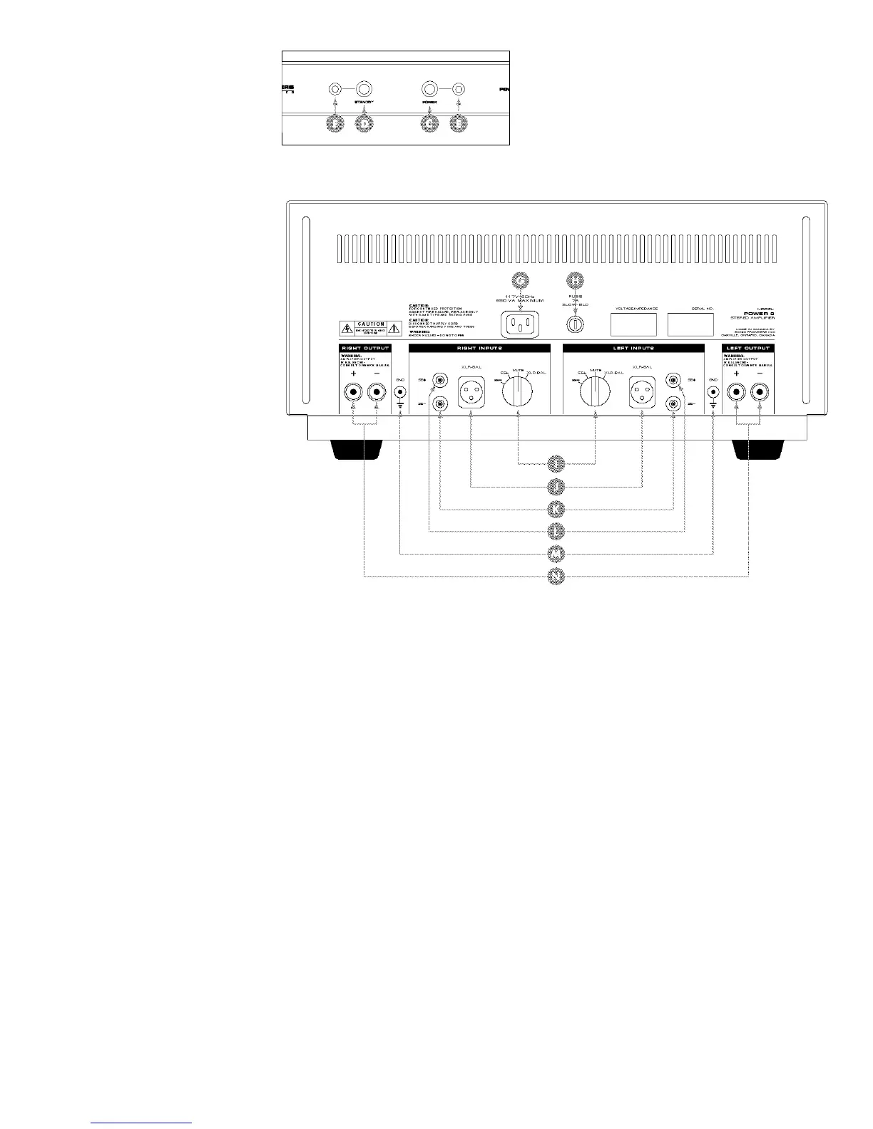
C Power Switch
D Standby Switch
E Power LED (Green - Power; Red - Mute; Orange (Red + Green)
- One Channel in Mute)
F Standby LED (Green - Operate; Red - Standby)
G Detachable IEC Power Cord Socket
H Fuse Location
I Left and Right Channel Input Selector Switches
J Left and Right Channel Balanced XLR Inputs
K Left and Right Channel Single-Ended RCA Inverting Inputs
L Left and Right Channel Single-Ended RCA Non-Inverting Inputs
M Left and Right Channel Ground Posts
N Left and Right Channel Loudspeaker Binding Posts
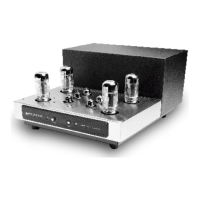
This drawing is referred to
as the “Front Panel” within
the instructional text.
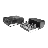
This drawing is referred to
as the “Rear Panel” within
the instructional text.