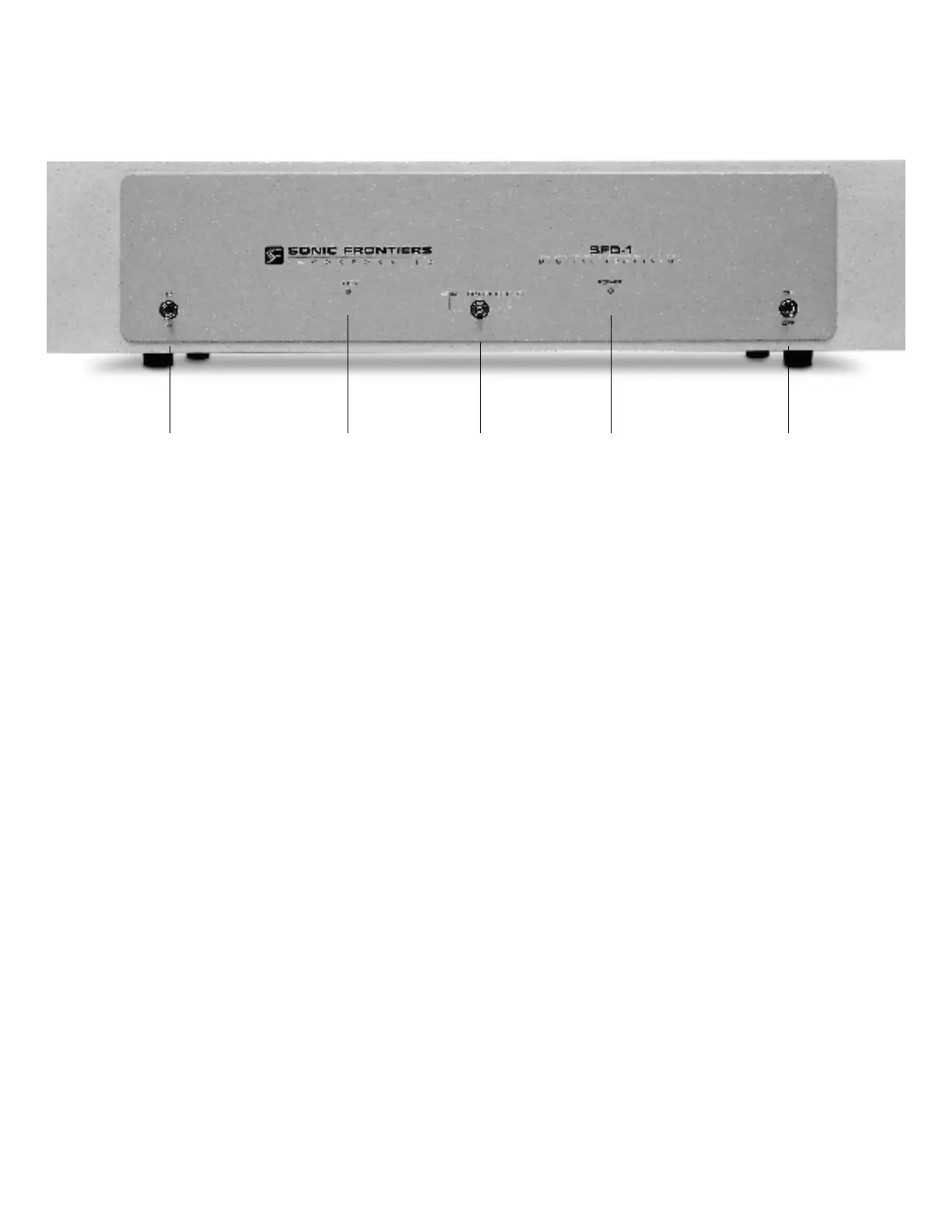
CONTROL FUNCTIONS AND CONNECTIONS
A
-Phase Control Switch - This toggle switch allows the user
to invert the system phasing easily and safely. When the switch
is in the 0° position the SFD-1 will put out a normal or non-
inverted signal in relation to the signal being received from the
source. When the switch is in the 180° position the SFD-1 will
put out an inverted version of the signal as compared to that
being received from the source. This feature offers a convenient
method of correcting source material which was recorded “out
of absolute phase” or to counteract for a component in your
system such as a preamplifier, power amplifier or signal con-
nection which inverts phase.
B - Signal Locking Indicator LED - This LED will light when
an operational digital source is selected.
NOTE: Depending on the source or transport being used in
conjunction with the SFD-1, it may be necessary to have the
source unit in the “play” mode and the SFD-1 receiving the dig-
ital transmission before the LED will light.
C - Input Selector Switch - This 3 position toggle switch
selects between the three digital inputs located on the back of
the SFD-1: Toslink (Plastic Fibre) Optical, RCA Coaxial Cable
and ST (Glass Fibre) Optical. A connection to all 3 inputs may
be made from 3 separate sources. The Signal Locking
Indicator LED (B) will light when the source is activated in con-
junction with the input chosen by this switch.
D
-Power Indicator LED - This LED will light when the Power
Switch (E) is in the ON position and the SFD-1 is receiving
p o w e r .
E - Power Switch - This toggle switch, when switched to the
ON position, allows the SFD-1 to receive power, rendering the
SFD-1 operational as indicated by the Power Indicator LED (D).
When the switch is in the OFF position the SFD-1 is not receiv-
ing power and is not operational.
A B C D E
 Loading...