6
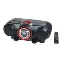
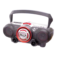
CFD-G70
SECTION 3
DISASSEMBLY
Note : Follow the disassembly procedure in the numerical order given.
3-1. CABINET (FRONT) ASSY, CABINET (REAR) ASSY
z
The equipment can be removed using the following procedure.
Set
Cabinet (front) ASSY
Cabinet (rear) ASSY Cabinet top ASSY LCD board
AC inlet board, Power board,
VOL SEL board (E4 model)
BATT board,
BATT COM board
Main board
Tuner board
CD board, TC board,
Optical pick-up block,
Mechanism deck
M321 (Capstan/Reel motor),
Belt, HRP301 Head, magnetic,
HE301 Head (Erase)
Optical pick-up (KSS-213C)
Control-1 board, Control-2 board Headphone board
1
8
4
2
Screw
(+BVTP 3
×
20)
2
Screw
(+BVTP 3
×
20)
5
Screw
(+BVTP 3
×
10)
6
Flexible cable
(from Main board CNP805)
7
Connectors
(from Headphone board CN391, 394, 396)
3
Screws
(+BVTP 3
×
14)
3
Screws
(+BVTP 3
×
14)
3
Screws
(+BVTP 3
×
14)
Cabinet (rear) ASSY
Cabinet (front) ASSY
Lid, battery case
• Abbreviation
E4 : 110-120V/220-240V AC changeable

 Loading...