Do you have a question about the Sony DCR-DVD306E and is the answer not in the manual?
Details on video/audio formats, discs, recording times, and system parameters.
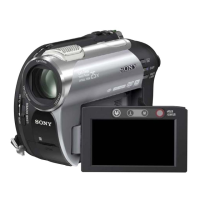
Information on lens, image sensor, viewfinder, and color temperature.
Specs related to power requirements, physical dimensions, and weight.
List of items included with the product package.
Important warnings regarding laser, battery, and general handling safety.
Guidelines for replacing critical safety components with specified parts.
Essential checks to perform after service to ensure safe operation.
Technical notes and characteristics of unleaded solder usage.
Procedure for maintaining power supply during repair operations.
Instructions on how to manually eject a disc that is not releasing.
Guidance on connecting and using the service jig for diagnostics.
Explanation of the self-diagnosis system and its display.
Table mapping self-diagnosis codes to symptoms and corrections.
Important precautions and notes before proceeding with disassembly.
Step-by-step guide for disassembling the main external components.
Procedure for disassembling the left side cabinet and related parts.
Steps for accessing and removing the MD (mechanism) block.
Procedure for disassembling the right side cabinet and internal components.
Instructions for removing and accessing the LCD panel and associated parts.
Diagrams showing the system's overall architecture, split into five parts.
Diagrams detailing the power supply and distribution within the system.
Overall layout diagram showing interconnections between major boards.
Detailed electronic circuit schematics for various boards and components.
Layouts showing component placement and trace routing on circuit boards.
Diagrams indicating the physical location of components on specific boards.
Illustrations showing parts breakdown of major assemblies for identification.
List of electronic components with part numbers and descriptions.
List of screws, fasteners, and other hardware with specifications.
| Fader | Black / White |
|---|---|
| Focus | 1.8-3.2 |
| I/O ports | Audio Out Video Out USB 2.0 |
| Display diagonal | 2.7 \ |
| Optical sensor size | 1/6 \ |
| Audio system | Dolby Digital 5.1 |
| Viewfinder resolution | 123 pixels |
| DV port | No |
| S-Video out | Yes |
| Camera shutter speed | 1/3-1/3500 s |
| Minimum illumination | 4 lx |
| Depth | 130.5 mm |
|---|---|
| Width | 54.5 mm |
| Height | 89 mm |
| Weight | 400 g |