DSC-F717
6-15
Picture Frame Setting
Mode CAMERA
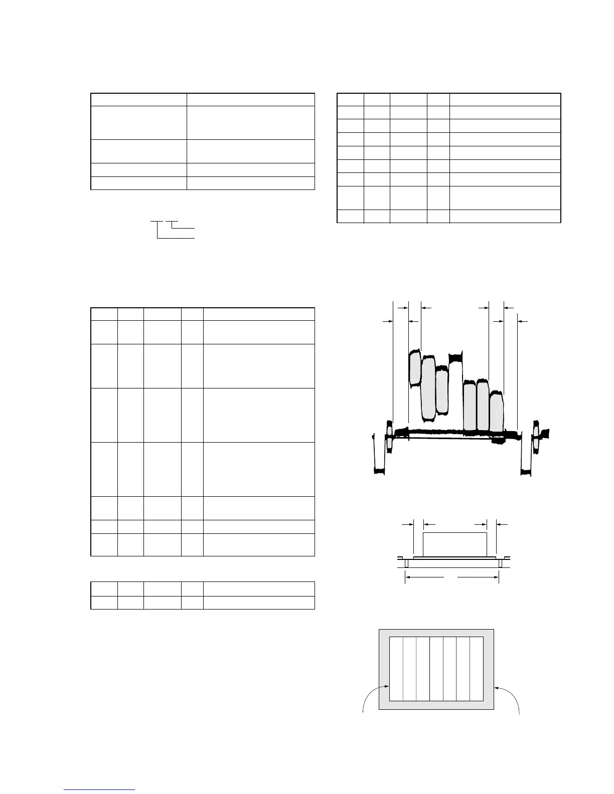
Subject Color bar chart
(Standard picture frame with the
zoom lens at WIDE end)
Measurement Point Video terminal of A/V OUT jack
(75 Ω terminated)
Measuring Instrument Oscilloscope and monitor TV
Specified Value A=B, C=D, E=F
Note 1: Displayed data of the page 1 of adjusting remote com-
mander.
1:XX:XX
YL data
YH data
Switch setting
1) FOCUS ....................................................... AUTO
2) MACRO (Control button)..........................ON
Setting method:
Order Page Address Data Procedure
1
Shoot the color bar chart
with the zoom WIDE end.
2
Enter the output of VIDEO
OUT to the monitor TV, and
move the position as shown
in Fig. 6-1-14.
3
Horizontal width of one color
(B, C) and that of black (A,
D) on the color bar chart
should be same. (See Fig. 6-
1-12)
4
With vertical width of black
(E, F) set in same, the color
bar chart should come to the
center of monitor TV. (See
Fig. 6-1-13)
5
Check that the color bar on
the monitor TV is focused.
6 0 03 22
71
Note down the YH and YL
data. (Note 1)
Processing after Completing Adjustment:
Order Page Address Data Procedure
1 0 03 00
How to reset the zoom and focus when they deviated:
Order Page Address Data Procedure
16 2C01
2 6 90 00
3 6 91 00
4 6 92 YL (Note 2)
5 6 93 YH (Note 2)
6 6 01 79 Press PAUSE button.
76 07
Check the data changes to
“01”.
8 6 01 00 Press PAUSE button.
Note 2: The data noted down at step 7 of “Setting method”.
Check on the oscilloscope
1. Horizontal period
Fig. 6-1-12
2. Vertical period
Fig. 6-1-13
Check on the monitor TV
Fig. 6-1-14
A=B
C=D
A
B
C
D

 Loading...