DSC-F717
6-41
5. Contrast Adjustment (PD-179 Board)
Set the level of the VIDEO signal for driving the LCD to the speci-
fied value.
If deviated, the LCD screen image will be blackish or saturated
(whitish).
Mode PLAY
Signal Arbitrary
Measurement Point Pin 9 of CN305 on FR-194
board (PANEL_VG)
External trigger: Pin 8 of
CN305 on FR-194 board
(PANEL_COM)
Measuring Instrument Oscilloscope
Adjustment Page A
Adjustment Address 8A
Specified Value A = 2.65 ± 0.07 Vp-p
Adjusting method:
Order Page Address Data Procedure
1 0 01 01
2 A 02 13 Press PAUSE button.
34 F103
4A 8A
Change the data and set the
voltage (A) to the specified
value.
5 A 8A Press PAUSE button.
Processing after Completing Adjustments:
Order Page Address Data Procedure
1 A 02 00 Press PAUSE button.
24 F100
3 0 01 00
6. V-COM Level Adjustment (PD-179 Board)
Set the common electrode drive signal level of LCD to the speci-
fied value.
Mode PLAY
Signal Arbitrary
Measurement Point Pin 8 of CN305 on FR-194
board (PANEL_COM)
Measuring Instrument Oscilloscope
Adjustment Page A
Adjustment Address 87
Specified Value A = 5.42 ± 0.05 Vp-p
Adjusting method:
Order Page Address Data Procedure
1 0 01 01
2 A 02 13 Press PAUSE button.
34 F103
4A 87
Change the data and set the
voltage (A) to the specified
value.
5 A 87 Press PAUSE button.
Processing after Completing Adjustments:
Order Page Address Data Procedure
1 A 02 00 Press PAUSE button.
24 F100
3 0 01 00
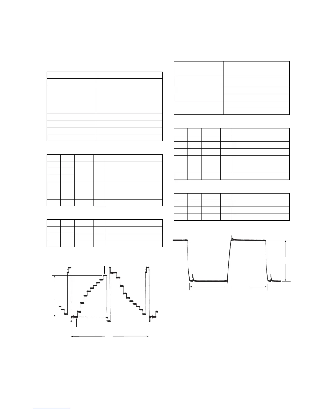
Fig. 6-1-20
A
2H
10 steps peak
Pedestal
A: Between the pedestal and 10 steps peak
Fig. 6-1-21
A
2H

 Loading...