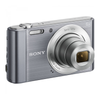
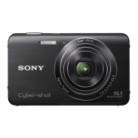
DSC-W830
4-3
4-3. MAIN BLOCK
4-3-1. Rear Cabinet Section
• Disassembly order
No. Part Item Note
1
Cabinet (Rear) Assy #212 or #293 x 5
Claw x 3
Refer to Note 1.
2
Side Cabinet (R)
3
Side Cabinet (L)
4
DC Lid Claw x 1
5
SW-1002 Board Claw x 2
Connector x 1
6
LCD Module Claw x 3
Connector x 1
7
LCD Insulating Sheet
8
Cabinet (Front) Assy #212 or #293 x 1 Refer to Note 1.
9
Cabinet (Upper) Assy #287 x 1
Claw x 3
0
Charging Capacitor Discharging of the Charging Capacitor. (Refer to next page).
#212 (Silver)
PINK/SILVER/VIOLET
#293 (Black)
BLACK
Cabinet's Color
Note1
For the combination of cabinet's color and screw,
please refer to Table 1-1.
Screw's Ref. No.
(Parts Color.)
Table 1-1
1.4
3.0
#212: M1.4 X 3.0
(Silver)
4-270-114-01
3
4
(Claw)
(Claw)
(Claws)
(Claw)
2
9
1
8
7
(Claw)
5
6
0
(Claw)
(Claw)
(Claw)
(Claw)
(Claw)
(Claw)
#212/#293 (8)
(Note 1)
#287 (9)
#212/#293 (1)
(Note 1)
#212/#293 (1)
(Note 1)
#212/#293 (1)
(Note 1)
#287: M1.4 X 5.0 (Tapping)
(Black)
4-188-736-21
5.0
1.4
#293: M1.4 X 3.0
(Black)
4-463-141-01
3.0
1.4
 Loading...