GTK-XB60
10
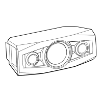
2-8. MAIN BOARD
7 Remove the MAIN board
block in the direction of
the arrow.
5 screw
(M3 u 10)
rear side
hole
9 MAIN board
Note:
When installing the MAIN board,
align the rib and hole.
:LUHVHtting
MAIN
board
terminal
side
XP11
XP13
XP7
A
A
B
B
3 FFC (TOP LED
-MAIN) (XP7)
4 POWER board cable
connector (XP20)
rib
2 woofer cable connector
(XP13)
1 tweeter cable connector
(XP11)
–7RSYLHZ–
FFC
(TOP LED-MAIN)
tweeter cable
woofer cable
rear side
XP20
8 thermal sheet
(See Fig. B)
6 four screws
(3 u 6)
left side
right side
)LJ%!
3DVWLQJSRVLWLRQRIWKHWKHUPDOVKHHW
When affixing the thermal sheet, affix so that the entire
projection of the bottom shell is covered.
thermal sheet
rear side
left side

 Loading...