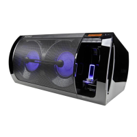
GTK-XB60
7
Note: Follow the disassembly procedure in the numerical order given.
2-2. SIDE PANEL L, LITHIUM ION BATTERY CONNECTOR (XP3)
top side
front side
rear side
4 five claws
4 four
claws
4 four
claws
1 two rubbers
(See Fig. A)
1 two rubbers
(See Fig. A)
+RZWRUHPRYHWKHUXEEHU
rubber
tweezers, etc.
–/HIWYLHZ–
Note:
When removing the rubber, insert a
sharp-tipped object such as tweezers
into the cutout.
)LJ$!
2 two screws
(M3 u 10)
2 screw
(M3 u 10)
3 three screws
(M4 u 20)
5 Remove the side panel L
in the direction of the arrow.
3 two screws
(M4 u 20)
6 side panel L
two bosses
(with two rubbers)
two bosses
(with two
rubbers)
7 lithium ion
battery
connector
(XP3)
MAIN board
front side
rear side
left side
2-3. LITHIUM ION BATTERY
top side
front side
rear side
boss
boss
1 four screws
(M4 u 20)
2 battery cover
Note 2:
When installing the battery cover,
align the two bosses and two holes.
6 lithium ion battery
hole
hole
3 Remove the lithium ion battery block
in the direction of the arrow.
10 mm
bottom side
top side
lithium ion battery
– Right view –
guide line
guide line
+Rw tR iQVtDOO the thUee FXVhiRQV
left side
right side
cushion (battery cable)
cushion (battery)
Wrap the cushion
(battery cable) around.
cushion (battery)
Wrap the cushion
(battery cable) around.
4 cushion
(battery cable)
Note 1:
This parts cannot be reused.
When replacing the lithium
ion battery, be sure to replace
them with new parts
simultaneously.
5 two cushions (battery)
Note 1:
This parts cannot be reused.
When replacing the lithium ion battery,
be sure to replace them with new parts
simultaneously.

 Loading...