EasyManua.ls Logo

Sony HCD-H881D User Manual

Sony HCD-H881D
83 pages
To Next Page IconTo Next Page
Page #1 background imageLoading...
Page #1 background image
MICROFILM
HCD-H881/H881D
RVC
ANA
—
@
HCD-H881/H881D
is
the
tuner,
deck,
CD
and
amplifier
section
in
MHC-81
1,
MHC-D7
and
MHC-G8s.
Dolby
noise
Dolby
Laboratories
Licensing
Corporation.
ā€œDOLBYā€
and
the
double-D
symbol
0)
are
trademarks
of
Dolby
Laboratories
Licensing
Corporation.
for
the
U.S.
model
AUDIO
POWER
SPECIFICATIONS
POWER
OUTPUT
AND
TOTAL
HARMONIC
DISTORTION
:
with
8
ohm
loads,
both
channels
driven,
from
40
-
20kHz
;
rated
100
watts
per
channel
minimum
RMS
power,
with
no
more
then
0.9
%
total
harmonic
distortion
from
250
milliwatts
to
rated
output.
CD
player
section
System
Compact
disc
and
digital
audio
system
Laser
Semiconductor
laser
Wavelength
780-790
nm
Frequency
response
2Hz-
20
kHz
(+0.5
dB)
Signal-to-noise
ratio
More
than
90
dB
Dynamic
range
More
than
90
dB
CD
DIGITAL
OUT
OPTICAL
(Square
optical
connector
jack,
rear
panel)
Wavelength
600
nm
Output
Level
-18
dBm
Tuner
section
FM
stereo,
FM
/AM
superheterodyne
tuner
FM
tuner
section
Tuning
range
US,
Canadian
model
:
87.5-
108MHz
(100kHz
step)
EXCEPT
US,
Canadian,
East
European
model
:
87.5-
108MHz
(50kHz
step)
East
European
model
:
FM
1
:
65—
74MHz
(10kHz
step)
FM
2:
87.5~
108MHz
(50kHz
step)
reduction
manufactured
under
license
from
MHe-881
Photo
:
HCD-H881
Tape
deck
Section
SPECIFICATIONS
Antenna
FM
lead
antenna
Antenna
terminals
75
ohm
unbalanced
Intermediate
frequency
10.7
MHz
AM
tuner
section
Tuning
range
US,
Canadian
model
:
531-
1,710kHz
(with
the
tuning
interval
set
at
9kHz)
530-
1,710kHz
(with
the
tuning
interval
set
at
10kHz)
AEP,
UK,
East
European,
German
model
:
MW
:
53i-
1,602kHz
(with
the
tuning
interval
set
at
9kHz
step)
LW
:
153-
279kHz
Italian
model
:
MW
:
522~
1,611kHz
(with
the
tuning
interval
set
at
9kHz
step)
LW
:
153-
279kHz
E,
Saudi
Arabia,
Argentine,
Hong
Kong,
Malaysia,
Taiwan,
Singapore,
Australian,
Tourist,
Indonesia,
CIS,
Mexican,
Thailand
model
:
531
-
1,602
kHz
(with
the
tuning
interval
set
at
9
kHz)
530
-
1,710
kHz
(with
the
tuning
interval
set
at
10
kHz)
SW
:5.95-
17.90MHz
(E3,
Saudi
Arabia,
Hong
Kong,
Tourist,
Malaysia,
Singapore,
Indonesia,
CIS
model)
an
Model
Name
Using
Similar
Mechanism
,
CD
Mechanism
Type
CDM38-5BD19
Section
ausaDI9
Model
Name
Using
Similar
Mechanism
Tape
Transport
Mechanism
Type
TCM-220WR2E
hear
Ae
US
Model
Canadian
Model
HCD-H881/H881D
AEP
Model
UK
Model
E
Model
Australian
Model
Tourist
Model
HCD-H881
Antenna
AM
loop
antenna,
External
antenna
terminals
Intermediate
frequency
450
kHz
Amplifier
section
AEP,
UK,
German,
Italian,
East
European,
CIS
model
:
DIN
50W+50W
(8
ohm,
1kHz,
0.8%
THD)
RMS
60W+60W
(8
ohm,
1kHz,
10%
THD)
MUSIC
power
output
105W+105W
(8
ohm,
1kHz,
10%
THD)
US,
Canadian
model
:
FTC
100W+100W
(8
ohm,
40-
20kHz,
0.9%
THD)
Continuous
RMS
_
power
output
120W+120W
(8
ohm,
1kHz,
5%
THD)
Other
model
Peak
music
power
output
1200
W
Continuous
RMS
power
output
80
W
+
80
W
(8
ohm
atl
kHz,
5
%
THD)
Inputs
VIDEO/MD
IN
(phono
jacks):
voltage
450
mV,
impedance
47
kilohm
MIX
MIC
(phone
jacks):
sensitivity
1
mV,
impedance
10
kilohm
—
Continued
on
page
2
—
MINI
HiFi
COMPONENT
SYSTEM
SONTY.
Question and Answer IconNeed help?

Do you have a question about the Sony HCD-H881D and is the answer not in the manual?

Sony HCD-H881D Specifications

General IconGeneral
Tuner BandsFM/AM
CD PlayerYes
Remote ControlYes
TypeMini Hi-Fi System
TunerDigital
SpeakersIncluded

Summary

Safety Check-out Procedures

Leakage Test Procedures

Procedure for measuring AC leakage current from exposed metal parts.

Servicing Notes and General Information

Servicing Notes

Precautions for handling optical parts, laser diodes, and jigs.

General Overview and Controls

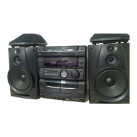
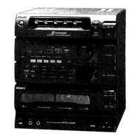
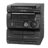
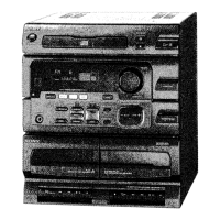
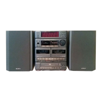
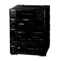
General information, index to parts, controls, and panel layout.

Disassembly Procedures

Component Removal Steps

Step-by-step instructions for disassembling front panel, CD block, and cassette mechanism.

Adjustment Procedures

Mechanical & Electrical Adjustments

Mechanical and electrical adjustments for tape deck functions.

Tape Speed, Level, and Bias Adjustments

Procedures for adjusting tape speed, playback level, record bias, and record level.

Tuner Section Operations

Tuner Repair Precautions & Tuning Adjustments

Precautions and level adjustments for FM, MW, and SW tuning.

FM Poler Adjustment (CIS Model)

FM Poler adjustment procedure specific to CIS models.

CD Section Operations

CD Focus, RF, and Waveform Checks

Procedures for CD focus bias, RF level, S-curve, and E-F balance checks.

Focus/Tracking Gain Adjustment Note

Note advising against performing focus/tracking gain adjustment.

IC Terminal Explanations

IC Terminal Functions

Explanation of terminals for key ICs like IC500 and IC701.

System Diagrams and Layouts

Block Diagrams (CD, Main Sections)

Block diagrams for CD section and main section (parts 1 and 2).

Circuit Board Locations

Diagram showing the location of various circuit boards within the unit.

Main Section PWB & Schematics

PWB layouts and schematic diagrams for the main section.

Panel Section PWB & Schematic

PWB layout and schematic diagram for the panel section.

BD Section PWB & Schematic

PWB layout and schematic diagram for the BD section.

TCB Section PWB & Schematic

PWB layout and schematic diagram for the TCB section.

Power Section PWB & Schematic

PWB layout and schematic diagram for the power section.

Audio Section PWB & Schematic

PWB layout and schematic diagram for the audio section.

Polar Section PWB & Schematic

PWB layout and schematic diagram for the polar section.

Exploded Views and Parts Lists

Exploded Views of Major Assemblies

Exploded views for chassis, front panel, mechanism decks, disc table, CDM chassis, and base unit.

Electrical and Hardware Parts

Comprehensive lists of electrical components and hardware used in the system.

Hardware List

Related product manuals