Sony HS-KP1 (US) 4-113-748-11(2)
Connecting the cables and installing the unit into the wall
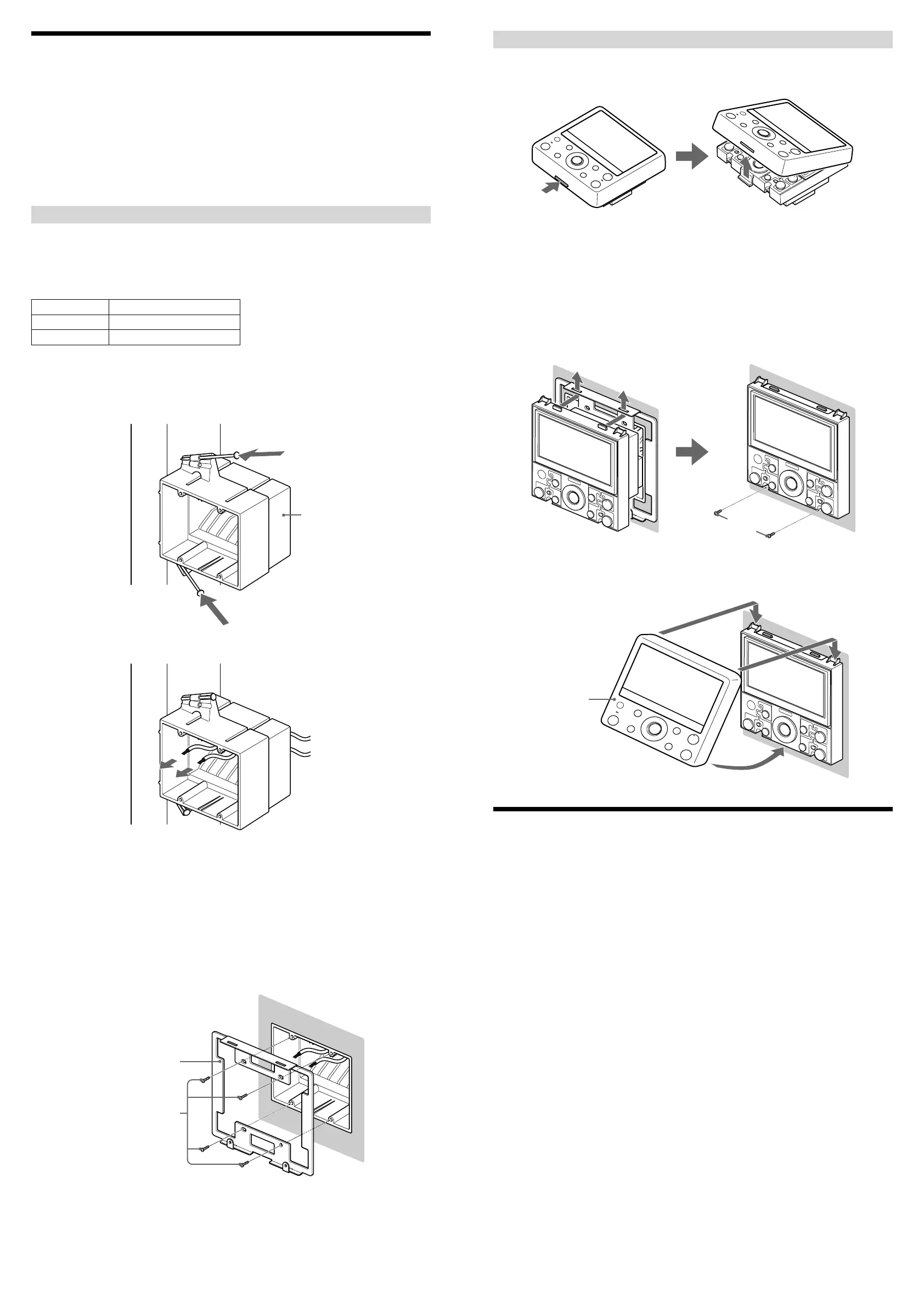
1 While pushing the tab at the bottom of the unit, remove the cover
panel. (The cover panel and unit are factory-packed separately.)
2 Attach RJ45 connectors to the ends of the CAT5 cables.
For details, see “Connecting RJ45 connectors to CAT5 cables.”
3 Connect the units using the CAT5 cables.
For details, see “Connecting speaker cords or power supply cords” and “Part names and descriptions.”
4 Insert the rear of the unit into the 2 gang J-box, and insert the two
tabs on the top of the unit into the holes of the wall mounting
bracket. Then fasten the bottom part of the unit with the screws
(supplied) with the wall mounting bracket.
Screws for the unit (short)
5 Hook the cover panel on the two tabs on the top of the unit first,
and then push the bottom part until the panel clicks into place.
Cover panel
Specifications
LCD
4.3 inch color TFT
GUI/NTSC for Camera and Monitor
Intercom
Push to talk
Mic: Monaural
Speaker: Monaural
Audio
Rated Output Power at 2ch stereo (8 ohms 1 kHz, THD: 10%): 20 W + 20 W (Optimum performance*)
* Depending on the length of the CAT5 (Category 5e) cable connected to of the rear panel, or the length of
diameter of the cable connected to DC IN of the rear panel.
Input and Output connectors
RJ45: (only for connection to HS-MB1 (Distribution Panel) or HS-WV1 (AV Wall
Port))
(only for connection to HS-WA1 (Local Audio Wall Port))
Speaker output: Wire requirements: Copper Wire AWG 26 – 18
Outer diameter: 3 mm (0.12 inches), maximum
Strip away: 10 mm (0.4 inches)
DC IN: Wire requirements: Copper Wire AWG 26 – 18
Outer diameter: 3 mm (0.12 inches), maximum
Strip away: 10 mm (0.4 inches)
IR IN: Monaural mini-jack (ø 3.5 mm)
General
Power supply: DC 19.5 V (only HS-AC1 (Power Supply))
Power consumption: DC 19.5 V/0.5 A (when driving the 8-ohm speaker)
Operating temperature: 0 °C - 30 °C (32 °F - 86 °F)
Dimensions: 134 × 134 × 80 mm (5
3
/8 × 5
3
/8 × 3
1
/4 inches) (w/h/d)
Mass: 450 g (1 lbs 15
6
/8 oz)
Design and specifications are subject to change without notice.
Installing the Unit
Before installing the unit into the wall, take steps to ensure your safety and that of your surroundings. Check the
following:
You can connect speakers (nominal impedance 8 ohms or higher) to the unit. For details, see “Connecting
speaker cords or power supply cords.”
The necessary wiring such as CAT5 cables, speaker cords, power supply cords, or IR REMOTE cords varies
depending on your system.
The location of the speakers to make sure that speaker cords can be run between the unit and the speakers.
The durability of the wall. The thickness of the wall must be between 13 to 19 mm (
1
/2 to
3
/4 inches).
There are no obstructions, such as air, electrical, or water conduit near the location where the unit is installed.
There is enough space (over 15 cm (6 inches)) inside the wall. If the space available inside the wall is insufficient
or does not have proper ventilation, a malfunction of the unit may occur due to heat build-up.
Do not install the unit where it may get wet due to water or other liquids. This may cause a malfunction of the
unit.
Do not install the unit in a place where moisture condensation may cause a malfunction of the unit.
Installing a 2 gang J-box in a new construction
Be sure to install a 2 gang J-box on a stud before wall construction is finished, so that the unit can be placed in the
2 gang J-box after construction of the wall is finished.
Sony recommends:
Carlon
gang boxes
Part No. Description
BH235A, SC200A 2 gang J-box with nails
BH235S 2 gang J-box with screws
1 Prewire the CAT5 cables in the walls.
2 Place the 2 gang J-box on a stud, and then fasten it with the nails
or screws that came with the 2 gang J-box.
2 gang J-box
3 Run the CAT5 cables through the holes of the 2 gang J-box.
Note
Do not pull the cable in longer than necessary. The unit may not be placed in the 2 gang J-box because of the
extra length of the cable.
4 Cut a hole of 110 to 116 mm (4
3
/8 to 4
5
/8 inches) in width and 98
to 104 mm (3
7
/8 to 4
1
/8 inches) in length in the wall material. Then
attach it to the structure of the house, and finish the wall.
5 Place the wall mounting bracket (supplied) in the hole of the
finished wall, and then fasten it with screws (supplied) to the 2
gang J-box.
Wall mounting bracket
Screws for the wall
mounting bracket (long)
 Loading...