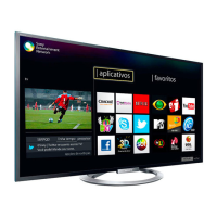
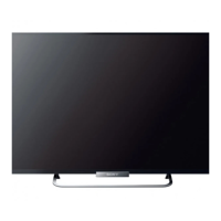
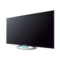
Do you have a question about the Sony KDL-42V4100 and is the answer not in the manual?
Procedure for removing the rear cover of the TV.
Steps to remove the switch unit and its associated H1 board.
Procedure to remove side jack bracket, BU shield, and BU board.
Steps for removing the G2D board, also known as the power unit.
Instructions for removing the table-top stand and the under cover.
Procedure for removing structural frames and various brackets.
Steps for removing speakers, under bar, H3E, H4K boards, and light guide.
Detailed steps for safely removing the LCD panel.
Procedure for removing the Balancer (ETC-Inverter MT) board.
Instructions for wire dressing on the left panel inverter.
Instructions for wire dressing on the right panel inverter.
Procedure for installing and dressing harnesses on the TV panel.
Step-by-step guide for dressing the AC cord in the undercover.
Information on viewing pre-set service adjustment data for optimal viewing.
Instructions on how to enter the TV's service adjustment mode.
Guidance on navigating and viewing the TV's service menus.
How to use the remote commander to access and adjust service data.
Procedure to restore user controls and settings to factory defaults.
Diagram showing the location of various circuit boards within the TV.
Key to symbols and notations used in schematic diagrams and wiring.
Overview of the TV's internal system architecture and signal flow.
Detailed schematic diagrams and supporting technical information for various boards.
Reference guide for semiconductor component identification and types.
Exploded view of the TV's rear cover and stand assembly components.
Diagram illustrating the main chassis components and their layout.
Identification and layout of various connectors on the TV's boards.
Exploded view of the bezel assembly and the LCD panel components.
Reference guide for screw types, part numbers, and their usage locations.
List of complete BU board parts for US and Canadian models.
Detailed list of all capacitor components with part numbers and values.
Detailed list of all resistor components with part numbers and values.
| Screen Size | 42 inches |
|---|---|
| Resolution | 1920 x 1080 |
| Display Type | LCD |
| Backlight Type | CCFL |
| Contrast Ratio | 3000:1 |
| Refresh Rate | 60 Hz |
| HDMI Ports | 3 |
| USB Ports | 1 |
| Weight | 33.1 lbs |
| Aspect Ratio | 16:9 |
| Response Time | 8 ms |
| Component Video Inputs | 1 |
| Composite Video Inputs | 1 |
| PC Input | 1 |
| Audio Output | 10W x 2 |
| Viewing Angle | 178 degrees |
| Input Ports | HDMI, Component, Composite, PC |


 Loading...