EasyManua.ls Logo

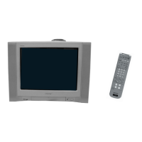
Sony KV-2199XFJ Trinitron User Manual

Sony KV-2199XFJ Trinitron
46 pages
To Next Page IconTo Next Page
Page #1 background imageLoading...
Page #1 background image
MODEL COMMANDER DEST. CHASSIS NO.
KV-2199XF
RM-952 ME SCC-U16N-A
KV-2199XFJ
RM-952 ME SCC-U16K-A
MODEL COMMANDER DEST. CHASSIS NO.
CHASSIS
TRINITRON
®
COLOR TV
SERVICE MANUAL
BG-3S
Self Diagnosis
Supported model

Questions and Answers:

Sony KV-2199XFJ Trinitron Specifications

General IconGeneral
BrandSony
ModelKV-2199XFJ Trinitron
CategoryTV
LanguageEnglish

Summary

SPECIFICATIONS

SELF DIAGNOSTIC FUNCTION

DIAGNOSTIC TEST INDICATORS

Lists diagnostic items, number of flashes, probable causes, and detected symptoms.

DISPLAY OF STANDBY/TIMER LIGHT FLASH COUNT

Illustrates the timing and counts for the standby/timer lamp flashes.

STOPPING THE STANDBY/TIMER FLASH

Instructions to stop the blinking standby/timer lamp after troubleshooting.

SELF-DIAGNOSIS SCREEN DISPLAY

How to display past error occurrences on the screen via remote commands.

HANDLING OF SELF-DIAGNOSTIC SCREEN DISPLAY

Procedures for clearing diagnostic results and quitting the self-diagnosis screen.

SELF-DIAGNOSTIC CIRCUIT

Explanation of circuit functions related to self-diagnostic error codes.

DISASSEMBLY

2-1. REAR COVER REMOVAL

Procedure for removing the rear cover of the TV unit.

2-2. CHASSIS ASSY REMOVAL

Steps for removing the main chassis assembly from the TV.

2-3. F BRACKET REMOVAL

Instructions for removing the F bracket component.

2-4. SERVICE POSITION

Guidance on placing the TV in a suitable position for service.

2-5. REPLACEMENT OF PARTS

General guidance on replacing internal components.

2-6. TERMINAL BRACKET REMOVAL

Steps for removing the terminal board bracket.

2-7. DEGAUSS COIL REMOVAL

Instructions for removing the degauss coil.

2-8. PICTURE TUBE REMOVAL

Procedure for safely removing the picture tube, including anode cap handling.

SET-UP ADJUSTMENTS

3-1. BEAM LANDING

Procedure for adjusting the beam landing for optimal picture alignment.

3-2. CONVERGENCE

Steps for adjusting the convergence of red, green, and blue electron beams.

3-3. FOCUS ADJUSTMENT

How to adjust the focus control on the flyback transformer for a sharp image.

3-4. G2 (SCREEN) AND WHITE BALANCE ADJUSTMENTS

Adjusting screen grid voltage and white balance for correct color reproduction.

3-5. SUB BRIGHT ADJUSTMENT

Procedure for fine-tuning the sub brightness level for optimal picture contrast.

CIRCUIT ADJUSTMENTS

4-1. ADJUSTMENTS WITH COMMANDER

Guide to entering service mode and performing adjustments using the RM-952 remote.

4-2. ADJUSTMENT METHOD

General explanation of how to adjust various parameters using the service remote.

4-3. PICTURE QUALITY ADJUSTMENTS

Adjustments for sub color and sub hue to optimize picture quality.

4-4. A BOARD ADJUSTMENT AFTER IC003 (MEMORY) REPLACEMENT

Steps for initializing and adjusting A board after memory IC replacement.

4-5. PICTURE DISTORTION ADJUSTMENT

Adjusting various picture distortion parameters like H/V position and size.

DIAGRAMS

5-1. BLOCK DIAGRAM

Overview of the TV's main functional blocks and signal flow.

5-2. FRAME SCHEMATIC DIAGRAM

Detailed schematic diagram of the TV's frame circuitry.

5-3. CIRCUIT BOARDS LOCATION

Diagrams showing the physical location of various circuit boards within the TV.

5-4. SCHEMATIC DIAGRAMS AND PRINTED WIRING BOARDS

Collection of schematic diagrams and printed wiring board layouts.

5-5. SEMICONDUCTORS

List of semiconductors used in the TV, with their part numbers and types.

EXPLODED VIEW

6-1. CHASSIS

Exploded view of the TV chassis, showing component identification and part numbers.

ELECTRICAL PARTS LIST

Related product manuals