7
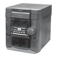
HCD-RG60
SECTION 3
DISASSEMBLY
3-1. CASE (SIDE-R, SIDE-L, TOP)
Note : Disassemble the unit in the order as shown below.
Note : Follow the disassembly procedure in the numerical order given.
Driver board, Moter board, Address sensor board
Chassis section
Case (Side-R, Side-L, Top)
CD door
Front panel section
CD mechanism deck
(CDM58B)
Key boardPanel boardTape mechanism deck
Sensor board, Sub trans board, Video out board, Back panel,
Surround board, DC fan, Power transformer (Trans board)
Main board, Power amp board
Base unit, BD board
Set
Case (Side-R)
Case (Side-L)
5
qd
qs
qs
q;
Case (Top)
6
Two screws (Case 3 TP2)
8
Screw
(+BVTP 3
×
10)
3
Screw
(+BVTP 3
×
10
9
Screw
(+BVTT 3
×
8)
4
Screw
(+BVTT 3
×
8)
1
Two screws
(Case 3 TP2)
qa
Four screws (+BVTP 3
×
10)
7
Screw (Case 3 TP2)
2
Screw (Case 3 TP2)
 Loading...