www.SteamPoweredRadio.Com
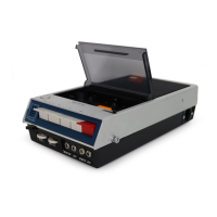
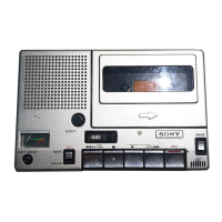
TC-150/8.
~T-50
4.
ELECTRICAL PARTS LIST
N
ote
:
Circled lettets (
®
to
(7))
are applicable to
European models only.
Ref
No.
Pa
rt
No.
Description
Ref.
No. Part No.
Description
SEMICONDUCTORS
C21
1·105-673•12@0.
0l
mylar
C22
l-105•719-12@0.033
l00V
mylar
®
Transistor
C23
1-105-669-
12@0.0047
mylar
Ql.2
2SC632A
C24
1·131-171-11@ 4. 7 16V
Q3,4
®
Transistor
2SC634A
C2S
l-131-170-11@ 3.3
l0V
QS
© Tra.nsistor
2SA678
Q6,7
@Tr
ansistor
2SC634A
C26
1-121-420·11® 220
I0V
electrolytic
Q8
@Trans
istor
2SC1474
C27 1-131-177-11© 100
3V
..
·
•·
-
1·131-256-
11©
10
.,
C28
l0V
IC!
®
1c
CX170
C29,30
1-102•074-l
1@0.001
ceramic
IC2
@
IC
BX295
C31
1-161-190-11@0.001
ceramic
@Diode
(boundary layer)
=>
O1-s
ISISSS
Thl
1·800-198-XX@Thermistor
S-lK
C32
1-102-074-11@ 0
.0
01
ceramic
C33
1-131-368-11@ 3.3
16V
C34
l-108-249-12@ 0.068
mylar
CAPACITORS
RESISTORS
'
All capacitors are
in
µF and
of
tantalum unless
othe
rw
ise
noted. (p
"'
µµF)
All resistors are in
n,
±s
%,
1
/16
W and carbon
SO
or
less working volts arc omitted except for
type unless otherwise noted.
electrolytic type.
1/a
W regular-type carbon resistors arc omitted.
Check schematic diagram for resistance values.
1-131-169•11@0.47
k
=
1000
Cl
l0V
C2
l-131·202-11@1.S
20V
C3
1-131-173-1 l
©
33
l0V
Rl
,2
1·209-878
-11@
1.8
k
C4
l-l0S-669-12@0
.0
047
mylar
R3
1·209-781-ll@l0k
C5
1-161-190-ll@0.001
ceramic
R8
1-210-381
·11@
33
k
(boundary layer)
Rl 2
1·209-768-11@2.2k
Rl3
1·210-113-11@
18
k
C6
1·10S
-669-12@0.0047
mylar
C1
l ·131·176-11
(6)
33"
3V
R14 1-210-3
71-11@
1.6 k
C8
1-107-123-11@47 p
silveted
mica
RlS
1-210-363-11@ 2
70
C9
1·131-170-11@3.3
l0V
R16
1·210-381-ll@
33
k
,.
1~131-174-11©47 l-210-363-11@ 270
"
CIO
6.3V
R19
R21
1·209-768·11@2.2k
Cll
1-131-173•11©33
l0V
Cl2
1-131-202-11
(6)
1.5
20V
R22 l-210-113-1
I@
18
k
CIJ
1-161-190-ll©0.0
01
ceramic
R23 1-209-774-11@ 5.1 k
(boundary layer)
R24
1·209•770-11@2.
7k
Cl
4
l-1Jl-173
•ll
©33
l0V
R2S
1-210-388-1 l@ 68 k
ClS
l-131-174-11@47
6.3 V
R26
1·210-392·11@7S
Cl6
1-
131-1
71-11@
4.
7
16V
R27
1·210~1
01
-11@
51
Cl7
1-121-419-11
(ID
220 6.3 V elec~rolytic
R28
1·210-846-11@ 33
Cl8
1-131-170-11@ 3.3
l0V
R29
1·209-770-11@2.7k
Cl
9 1-131-177-11 © 100
3V
R30
1-209-774-11@
S.l
k
C20 1-131
•2
44-ll
@ I
6.3V
R31 1-210-111·11@
12k
,..
Due
to
standardization, interchangeable replacements may
be
substituted for
paru
specified
in
the diagruns.
 Loading...