EasyManua.ls Logo

Sony TC-R303 - User Manual

Sony TC-R303
26 pages
To Next Page IconTo Next Page
Loading...
SERVICE MANUAL
US Model
Canadian Model
AEP Model
Dolby noise reduction manufactured under license from
Dolby Laboratories Licensing Corporation.
“DOLBY” and the double-D symbol
00
are trademarks of
Dolby Laboratories Licensing Corporation.
Recording system
4-track 2-channel stereo
Fast-forward and rewind time
Approx. 90 sec. (with C-60 cassette)
Bias frequency
105 kHz
Signal-to-noise ratio (NAB, at peak level)
Model Name Using Similar
t---
SPECIFICATIONS
Tape Transport Mechanism Type
TYPE II (Sony
UX
S)
Total harmonic distortion
B
TYPE
C-TYPE
ON ON
65dB
71 dB
64
dB
61 dB
70dB
67dB
1.0% (with Sony METAL-ES cassettes)
Frequency response
DOLBY NR OFF
l With TYPE
IV
cassette (Sony METAL-ES)
30
15,000 Hz (±3
dB)
30
13,000 Hz (±3 dB, 0 VU recording)
l With TYPE II cassette (Sony UX-S)
30 15,000 Hz
(±3
dB)
l With TYPE
I
cassette (Sony
HF-S)
20
14,000 Hz
(±3
dB)
Wow and flutter
0.07% WRMS (NAB)
inputs Microphone inputs (phone jacks)
Sensitivity 0.25
mV
(-70
dB)
For a low-impedance microphone
Line inputs (phono jacks)
Sensitivity 77.5
mV
(-20
dB)
Input impedance 47 kilohms
outputs
Line outputs (phono jacks)
Output level 0.44 V
(-5
dB)
at load
impedance 47 kilohms
Load impedance over 10 kilohms
Headphones output (stereo phone jack)
Output level -28
dB
at load impedance
8 ohms
General
Power requirements
USA and Canadian
model: 120
Vac,
60 Hz
UK model: 240V ac,
50/60Hz
AEP model: 22OV ac, 50/60 Hz
Power consumption
20 Watts
Dimensions
Approx. 430
x
110 x 255 mm (w/h/d)
(17 x
4%
x
10% inches)
including projecting parts and controls
Weight
Approx. 3.9 kg (8 Ibs 10 oz)
SAFETY-RELATED COMPONENT WARNING!!
COMPONENTS IDENTIFIED BY SHADING AND MARK
A
ON THE SCHEMATIC DIAGRAMS AND IN THE
PARTS LIST ARE CRITICAL TO SAFE OPERATION.
REPLACE THESE COMPONENTS WITH SONY PARTS
WHOSE PART NUMBERS APPEAR AS SHOWN IN THIS
MANUAL OR IN SUPPLEMENTS PUBLISHED BY SONY.
ATTENTION AU COMPOSANT AYANT RAPPORT
A LA
SECURITE
LES COMPOSANTS
IDENTIFIES
PAR UNE TRAME ET
UNE MARQUE
h
SUR LES
DIAGRAMMES
SCHE-
MATIQUES
ET
LA
LISTE
DES
PIECES
SONT CRITIQUES
POUR LA
SECURITE
DE FONCTIONNEMENT. NE
REM-
PLACER CES COMPOSANTS DUE PAR DES
PIECES
SONY DONT LES
NUMEROS
SONT
DONNES
DANS CE
MANUEL OU DANS LES SUPPLEMENTS
PUBLIES
PAR
SONY.
STEREO CASSETTE DECK
SONY
w
w
w
.
x
i
a
o
y
u
1
6
3
.
c
o
m
Q
Q
3
7
6
3
1
5
1
5
0
9
9
2
8
9
4
2
9
8
T
E
L
1
3
9
4
2
2
9
6
5
1
3
9
9
2
8
9
4
2
9
8
0
5
1
5
1
3
6
7
3
Q
Q
TEL 13942296513 QQ 376315150 892498299
http://www.xiaoyu163.com
Question and Answer IconNeed help?

Do you have a question about the Sony TC-R303 and is the answer not in the manual?

Sony TC-R303 Specifications

General IconGeneral
BrandSony
ModelTC-R303
CategoryCassette Player
LanguageEnglish

Summary

General Specifications

General Specifications

Details power requirements, consumption, dimensions, and weight of the cassette deck.

Safety Component Warning

Highlights critical components for safe operation and emphasizes using specified replacement parts.

Model Identification and Safety Procedures

Model Identification and Regional Specs

Identifies regional models and their specific power requirements (US, Canadian, AEP, UK).

Safety Checks and Leakage Test

Outlines mandatory safety checks for US models and procedures for AC leakage testing.

Controls and Connections

Front Panel Controls

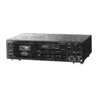
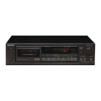
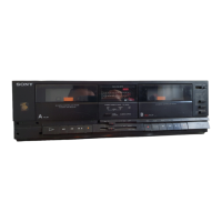
Describes buttons, jacks, and indicators on the front of the unit.

Rear Panel Connections

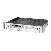
Details input/output jacks and sync connectors on the rear panel.

Front Panel Control Details

Front Panel Indicators and Switches

Explains operational indicators, switches, input jacks, and selectors on the front panel.

System Block Diagram

System Block Diagram

Illustrates the overall signal flow and major functional blocks of the device.

Adjustments

Mechanical Adjustments

Details procedures and torque measurements for mechanical part calibration.

Electrical Adjustment Overview

Outlines general settings and procedures for electrical calibration, including switches and controls.

Specific Adjustments

Tape Speed and Head Azimuth Adjustment

Procedures for calibrating tape playback speed and aligning the record/playback head for optimal sound.

Playback Level and Record Bias Calibration

Adjusting playback output levels and record bias settings for optimal performance.

Record Level Adjustment

Procedure for setting and verifying the recording input level.

Diagrams

Semiconductor Lead Layouts

Visual representation of semiconductor pin configurations and types.

Mounting Diagrams

Illustrates the physical placement of components on circuit boards.

Schematic Diagrams

Detailed circuit schematics showing electronic components, signal flow, and connections.

Parts Lists

Exploded Views and Parts Identification

Visual breakdown of parts with their corresponding numbers for assembly and repair.

Electrical Parts List

Comprehensive list of electronic components with part numbers, values, and specifications.

Troubleshooting

Function Button and Transport Issues

Common problems related to control buttons and tape movement.

Recording and Playback Problems

Troubleshooting for issues like no sound, low level, or poor reproduction and signal quality.

Noise Troubleshooting

Diagnosing and resolving hum noise or recorded interference from external sources.

Related product manuals