Do you have a question about the Sony TCM-500DV and is the answer not in the manual?
Guidelines for repairing flexible circuit boards.
Precautions for replacing chip components.
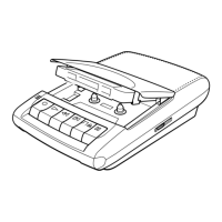
Steps to disassemble the cabinet rear and lid assembly.
Procedure for removing the main board.
Steps to detach the mechanism deck.
Procedures for accessing the head, belt, and motor.
Steps to calibrate the tape speed.
Electrical schematic for the main board (first half).
Electrical schematic for the main board (second half).
| Brand | Sony |
|---|---|
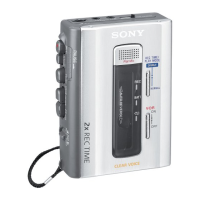
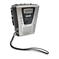
| Model | TCM-500DV |
| Recording Media | Compact Cassette |
| Recording System | Analog |
| Signal-to-Noise Ratio | 50 dB |
| Wow and Flutter | 0.25% (WRMS) |
| External Microphone Input | Yes |
| Headphone Jack | Yes |
| Battery Type | AA |
| Number of Batteries | 2 |
| Type | Cassette Player |
| Microphone | Built-in |
| Power Source | Battery |
| Fast Forward/Rewind Time | Approx. 90 seconds |