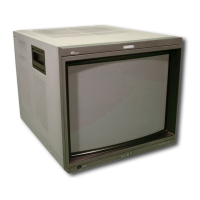
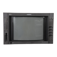
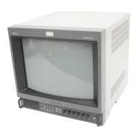
Do you have a question about the Sony TRINITRON BVM-14F5E and is the answer not in the manual?
Do not expose the unit to rain or moisture, and do not open the cabinet. Refer servicing to qualified personnel.
Caution regarding the danger of explosion if the battery is replaced incorrectly and proper disposal.
The socket-outlet should be installed near the equipment and be easily accessible.
Specifies the use of UL LISTED power cords for USA operation and prohibits other types.
Details FCC rules for Class A digital devices, potential interference, and modification warnings.
Emphasizes that the apparatus must be earthed and provides wiring color code information.
Explains CE marking compliance with EMC and Low Voltage Directives and lists relevant European standards.
Guidelines for safe operation including power, handling spills, cords, and socket-outlet installation.
Recommendations for installation concerning air circulation, heat sources, and environmental factors.
Instructions for cleaning the unit and precautions to avoid damage.
Warnings about magnetism affecting picture quality and careful handling of the CRT surface.
General introduction to the BVM-series Trinitron color video monitors and their suitability for professional use.
Highlights features like high-resolution picture tube, auto alignment, expandable inputs, dual aspect ratio, and menu operation.
Details other features like ISR system, test signal generator, VITC reader, and rack mounting compatibility.
Lists optional control units (BKM-10R/11R), memory card, and auto setup probe.
Describes optional masks for aspect ratio display and rack mount kits for installation.
Explains the function of decoder and input expansion adaptors for customizing input configurations.
Details SDI adaptors (BKM-20D, BKM-21D, BKM-22X) for digital signal inputs.
Lists analog composite, PAL-M, and Y/C signal adaptors (BKM-24N to BKM-27T).
Describes analog input expansion adaptors (BKM-28X, BKM-48X) for increasing input channels.
Explains how to configure input/output connectors using optional adaptors and the INPUT CONFIGURATION menu.
Provides a table detailing which signal types are supported by various decoder and expansion adaptors.
Explains the priority order for selecting decoder adaptors when multiple are installed in the monitor.
Provides installation instructions for BKM-20D/21D adaptors, including order and radiation shield handling.
Identifies and illustrates the controls and indicators on the front panel of the BVM-14F5U/E and BVM-14E5U/E models.
Identifies and illustrates the controls and indicators on the front panel of the BVM-20F1U/E, BVM-20E1U/E, and BVM-14F1U/E, BVM-14E1U/E models.
Explains the function and control of the Tally lamp and the main POWER switch.
Describes the DEGAUSS button, numeric keypad for input selection, and manual adjustment knobs.
Details the function of the POWER, STANDBY, and OVER LOAD indicator lamps.
Identifies and describes the rear panel connectors, slots, and switches including AC IN, REMOTE, and ISR ports.
Detailed description of analog input/output connectors, signal types, and loop-through capabilities.
Details the REMOTE 1 connectors for serial control and input option slots for adaptors.
Explains the pin assignments and functions of the REMOTE 2 connector for parallel remote control.
Specifies the ISR connector type and its purpose for status reporting.
Instructions for inserting and ejecting the monitor memory card, with a caution note.
Describes the function of the OPTION connector for connecting control units or probes.
Explains the MAIN POWER switch operation and the AC IN connector for power supply.
Details the fuse, deflection option slot, and the control unit connector for external control.
Detailed description of analog input/output connectors, signal types, and loop-through capabilities.
Explains the RS-485 serial interface via REMOTE 1 connectors for multi-monitor control.
Lists the pin functions for the REMOTE 2 connector and how to enable/disable functions via pin connections.
Specifies the ISR connector type and its purpose for status reporting.
Explains the role of each button on the front panel for navigating and operating the on-screen menus.
Describes how to display and navigate the main menu and its levels using front panel buttons.
Summarizes the purpose of each main menu category, such as CONTROL PRESET ADJ, COLOR TEMP ADJ, and SET UP.
Explains the notation used for menu numbers to indicate selection paths within the menu system.
Describes the ADDRESS menu for selecting specific monitors or groups for remote control.
Visual representation of the menu system hierarchy from the main menu down to level 2, with page references.
Details the constituent menus for setting preset values for contrast, brightness, chroma, and phase.
Step-by-step guide on how to display menus, select items using cursor keys or the PHASE knob, and confirm settings.
Explains how to adjust settings by selecting from lists, entering numerical values, and confirming choices.
Details procedures for selecting options from lists and entering numerical data for settings.
Guides on entering text for channel names and correcting errors using the Del button.
Describes methods for setting numerical values using the keypad, UP/DOWN buttons, or PHASE knob.
Introduces the menu for preliminary adjustment of picture levels (contrast, brightness, chroma, phase) using preset values.
Details the menu structure and the functions of constituent menus like PRESET, CH SET, MANUAL, AUTO, and COPY.
Explains manual adjustment using knobs and automatic adjustment using a color bar signal.
Details options for copying preset data from other channels, monitors, or memory cards.
Introduces the menu for adjusting color temperature, allowing common or individual channel settings.
Outlines the three methods for color temperature adjustment: knob adjustment, automatic adjustment using a probe, and data copying.
Displays the hierarchical structure of the COLOR TEMP ADJ menu, showing paths to various settings.
Explains how to select standard, common, or channel-specific color temperature data.
Details the MANUAL menu for knob adjustments and the COPY menu for transferring color temperature settings.
Guides on using probes for automatic adjustment (ADJUST) and analyzing performance (ANALYZE).
Explains how to copy color temperature settings from other sources like monitors or memory cards.
Details copying color temperature data from other values, monitors, or memory cards, including specific menu paths.
Explains the TRIM menu for fine-tuning gain and bias adjustments and resetting values.
Describes how to apply or not apply fine adjustments (TRIM) to the original settings and select the white signal source.
Guides on setting input signal data, including channel numbers, input connectors, and signal types/formats.
Details how to assign signal types (digital, analog, Y/C) and formats, listing required adaptors for each.
Illustrates the structure of the INPUT CONFIGURATION menu, showing paths to FORMAT, SCREEN MODE, CHANNEL NAME, and COPY settings.
Explains settings for signal format, Y/C separation, sync mode, screen mode, safe area, and aperture.
Covers setting channel names, controlling preset/channel-specific values, color temperature, and copying data.
Details the composite signal format settings, including AUTO detection and specific NTSC, PAL, PAL-M, SECAM options.
Explains configuration for component, serial digital (SDI), and Y/C signals, including format options.
Covers Y/C separation filter selection and screen mode settings for aspect ratio and overscan/underscan.
Explains how to scale safe area display and assign custom names to channels.
Explains the use of serial (REMOTE 1) and parallel (REMOTE 2) control, including priority and simultaneous operation.
Details setting monitor addresses and group numbers for controlling multiple monitors via the REMOTE menu.
Covers setting monitor address, group address, and remote mode for serial control.
Details assigning functions to REMOTE 2 connector pins, including aspect ratio, sync, display modes, and power control.
Introduces the PASSWORD menu for setting a four-digit password to restrict access to menu settings.
Explains how to change the password and apply it to specific menu items for protection.
Details the process of entering and confirming a new password to set up protection.
Describes how to select which menus will require password entry for access.
Covers methods for channel number entry and configuring power-up conditions and default channels.
Details settings for degauss delay, AFC time, residual subcarrier, auto chroma control, and contrast/brightness hold.
Explains channel entry methods (DIRECT/10KEY), standby modes, and default channel selection.
Details settings for degauss delay, AFC time, residual subcarrier, ACC switch, contrast/brightness hold, and color temperature shortcut.
Guides on setting the display of VITC, user bits, caption vision, and SDI ancillary data on the screen.
Covers configuring the display mode for channel numbers and channel names.
Explains how to enable/disable VITC, user bits, captions, and select channel number/name display modes.
Details selecting the display positions for VITC, channel number, and channel name on the screen.
Introduces the ALIGNMENT menu used for adjusting screen convergence and geometry.
Covers settings like ROTATION, H PHASE, V CENTER, H SIZE, and V SIZE for picture geometry correction.
Details adjustments for pincushion distortion (H PIN, H CORNER PIN) and horizontal linearity (H LIN).
Explains various settings for vertical and horizontal convergence adjustments across different screen areas.
Outlines the four main functions available through the EXTEND menu: factory data restore, memory card operations, monitor restart, and signal adjustment.
Guides on reloading factory default data to boards and performing backup/restore operations with the memory card.
Covers restarting the monitor and adjusting internal signal levels for white balance.
Details the process of restoring system data from the memory card to the monitor.
Covers restarting the monitor and adjusting internal signal levels using the ADJ INT SIGNAL function.
Introduces the MEMORY CARD menu for managing data on the monitor memory card.
Explains functions for saving, loading, deleting files, and formatting the memory card.
Introduces the COPY menu for sharing setup and adjustment data between connected monitors.
Details how to copy all settings, or specific settings like Control Preset, Color Temp, or Setup, using monitor addresses.
Introduces the STATUS menu for viewing general monitor data and signal assignments to rear panel slots.
Explains how to view channel status (input number, format) and slot status (installed options).
Explains how to select specific monitors or groups for remote control using the ADDRESS menu.
Details notes on remote control modes (SINGLE, GROUP, ALL) and potential issues with memory card operations.
Instructions for cancelling remote control mode and exiting the ADDRESS menu.
Describes shortcuts for quickly selecting monitors in SINGLE, GROUP, or ALL modes.
Lists the accessories included with the monitor, such as power cord, fuse, and operation manual.
Provides diagrams and pin assignments for connection cables used with Graseby SLS 9400 color temperature probes.
Details CRT specifications like aperture grille pitch, deflection, and nominal chromaticity coordinates for different phosphors.
Lists power supply requirements, consumption figures, and peak inrush current characteristics.
Provides physical dimensions, mass, and dimensional drawings for various BVM monitor models.
Describes the types and specifications of video input, sync input, remote control, and option connectors.
Details specifications for video signal quality (gain, phase, frequency response) and synchronization timing.
Covers picture performance metrics like linearity and convergence, as well as environmental operating conditions.
Shows the connection cable diagram and pin assignments for the Graseby SLS 9400 probe.
Details the connection cable diagram and pin assignments for the Minolta CA-100 probe.
Provides the connection cable diagram and pin assignments for the Philips PM 5639 probe.
Shows the connection cable diagram and pin assignments for the Thoma TF6 probe.


