EasyManua.ls Logo

Sony WM-EX50 Service Manual

Sony WM-EX50
30 pages
To Next Page IconTo Next Page
Page #1 background imageLoading...
Page #1 background image
WM-EX90/FX90
SERVICE
MANUAL
WM-EX50
TABLE
OF
CONTENTS
GENERAL:
.
westecsstinpiessiniiocntetcncetasanueiaenenaarmnes
2-
6
Messages,
warnings
and
tipS.........ccsssccccessessseeeeeees
2
Test
equipment,
Jigs
and
material
.................006
3
PCAGURG:
Gls
si4
sup
cehnetabaaashovecaevuusenisasoucieen
erseemaacmorses
3
Location
and
function
of
controls
...................0ee
4
User’s
instruction
(WM-EX50
only)
..............
5-
6
DET
VICE
MOLES:
ivivavelpesgbadvortabecsieesstianvbocecoussJemeeveee
6
FRE
MOV
AT
ccsccrcvasticsrest
titers
cueviausdestandivscnutanne
nus
eews
ri
LCD
BLOCK
INFORMATION(WM-EX50
only)....
8
Data
code
chart
and
indication
mode
.................
8
BLOCK.
DIAGRAMS
xeiisssct
sasccnssmunsacchietearlinss
ees
9-10
SCHEMATICS
AND
BOARD
DIAGRAMS
.......
11-19
Semiconductor
layouts
...........cccccsssssssecceeeeeeeeeeenes
14
POC
Fey
GUE
Ses
haces
neve
veteh
cen
on
eshite
ce
baesios
cau
Qaeusecesncenrcnsawents
19
SPARE
PARTS
LIB
DE
ncdGuteecokecetitiaiacs
20-28
Exploded
views
and
mechanical
parts............
20-22
Electrical
parts
cctusctascnctiicenitiaciintivacewsn
23-28
ADUOSTIMERINGS:
sites.
dsSieoessaints
ceuurelstecbentetedecaines
29-32
Mechanical
measurements
...........ceeeeeseeeeeeeeeeneeees
29
Mechanical
adjustments
...............ceeeeeeeseseeneeeeeeeeee
29
Electrical
alignments
........cccesscceseeeeeeeeeeeetees
30-32
Adjustment
location
s...cicccccicccasscnvsessicnorersseness
29-30
SPECIE
IC
A
TIONS
s.fius
pe
coccedecteadeceeccinusavedsvsperasniohs
34
US
Model
AEP
Model
E
Model
WM-EX50/FX50
UK
Model
WM-EX50
Canadian
Model
WM-FX50
WWN-FX50
WM-EX50
:
MT-WMEX50-01
Tape
Transport
Mechanism
WM-FX50
:
MT-WMFX50-01
Dolby
noise
reduction
manufactured
under
license
from
Dolby
Laboratories
Licensing
Corporation.
*DOLBY”
and
the
double-D
symbol
OO
are
trade-
marks
of
Dolby
Laboratories
Licensing
Corporation.
CASSETTE
PLAYER
WM-EX50
RADIO
CASSETTE
PLAYER
WM-FX50
SONY.
Question and Answer IconNeed help?

Do you have a question about the Sony WM-EX50 and is the answer not in the manual?

Sony WM-EX50 Specifications

General IconGeneral
TypeCassette Player
BrandSony
ModelWM-EX50
Mega BassYes
AVLS (Automatic Volume Limiter System)Yes
Remote ControlOptional
Wow and Flutter0.15% WRMS
Headphone Jack3.5 mm
Auto ReverseYes
Power Supply2 x AA batteries
HeadphonesIncluded
Playback ModesNormal
Frequency Response40 Hz - 15, 000 Hz
Output Power5mW + 5mW at 16 ohms
Dolby Noise ReductionDolby B

Summary

GENERAL

General Warnings and Precautions

Covers safety messages, battery warnings, and general precautions for operation.

Safety-Related Component Warnings

Highlights critical components marked with A for safe operation.

Power Precautions and Sources

Details on battery care, preventing leakage, and connecting external power.

Test Equipment and Features

Lists required test equipment and describes the double super heterodyne FM receiver feature.

Jigs and Materials

Lists specific jigs and materials required for servicing.

Location and Function of Controls

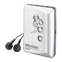
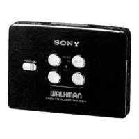
Explains the purpose and operation of all device controls.

Clock Setting Instructions

Step-by-step guide for setting the clock on the device.

Service Notes

Important notes for service personnel regarding operation checks and repairs.

REMOVAL

Tuner Unit Removal Procedure

Step-by-step instructions for removing the tuner unit from the cassette lid.

LCD BLOCK INFORMATION

LCD Display Modes and Indications

Explains LCD operation for clock and tape running indications.

Data Code Chart for LCD

Correlates data codes with LCD display modes for tape operation.

BLOCK DIAGRAMS

Tuner Section Block Diagram

Illustrates the signal path and component relationships in the tuner section.

AUDIO SECTION

Audio Section Block Diagram

Shows the signal flow and component layout for the audio processing circuits.

SCHEMATICS AND BOARD DIAGRAMS

Tuner Board Schematic Diagram

Detailed circuit diagram for the tuner board, showing component connections.

Tuner Board Printed Wiring Board Diagram

Visual layout of components and traces on the tuner board.

Audio Board Schematic Diagram

Detailed circuit diagram for the audio board, listing components and connections.

Audio Board Printed Wiring Board Diagram

Visual layout of components and traces on the audio board.

IC LAYOUTS

Integrated Circuit Pin Diagrams

Pinout and block diagrams for key integrated circuits used in the device.

SPARE PARTS LIST

Mechanical Parts Exploded View

Illustrated breakdown of mechanical parts with reference numbers for identification.

Tape Transport Components (Part 1)

Detailed list and diagram of tape transport mechanism components.

Tape Transport Components (Part 2)

Continuation of tape transport components list and diagrams.

ELECTRICAL PARTS

Electrical Parts: Capacitors

List of capacitor part numbers, types, values, and voltage ratings.

Electrical Parts: Inductors, Transistors, Diodes

Lists part numbers for coils, transistors, and diodes.

Electrical Parts: Resistors, Switches, Connectors

Lists part numbers for resistors, switches, variable resistors, and connectors.

Electrical Parts: Tuner Components, Filters

Lists part numbers for tuner board capacitors, trimmers, diodes, and filters.

Electrical Parts: Display Panel Components

Lists components for the flexible display panel block.

ACCESSORY & PACKING MATERIAL

Accessories and Manuals Supplied

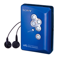
Details on included accessories, packaging, and instruction manuals for different models.

ADJUSTMENTS

Mechanical Measurements: Torque, Wow, Flutter

Procedures for measuring torque, wow, and flutter in the tape transport.

Tape Speed Adjustment Procedure

Procedure for adjusting the tape transport speed.

Tuner Section Electrical Alignments

Procedures for tuning voltage and FM/AM frequency adjustments.

FM Oscillator and VCO Calibration

Procedures for adjusting FM 2nd oscillator and VCO for optimal performance.

FM/AM Frequency Coverage Calibration

Procedures for fine-tuning FM and AM signal reception frequencies.

SPECIFICATIONS

Radio and Power Life Specifications

Technical details on radio frequency ranges and battery power life.

Power Requirements and Supplied Accessories

Information on power input, voltage compatibility, and included accessories.

Related product manuals