XLRハンドルユニット
XLR Handle Unit
Poignée XLR
XLR 手柄装置
取扱説明書/Operating Instructions/Mode d’emploi/
Manual de instrucciones/Bedienungsanleitung/
Gebruiksaanwijzing/Bruksanvisning/
Istruzioni per l’uso/Instruções de operação/
使用说明书/使用說明書/사용 설명서
XLR-H1
© 2022 Sony Corporation
Printed in Thailand
https://www.sony.net/
5-050-139-01(1)
取り扱い上のご注意
• 本機に接続可能なカメラについては、以下のサイトでご確認
ください。
こちらに記載がないソニー製カメラの場合は、本機と組み合
わせてお使いいただくことはできません。
https://www.sony.net/dics/h1/
• 本機を他社製品と組み合わせて使用した際の性能や、それによって生じた事故、
故障につきましては保証いたしかねますので、あらかじめご了承ください。
• 本 機 は 防 じ ん 、防 滴 、防 水 仕 様 で は あ り ま せ ん 。
• 火災、感電の原因となることがありますので以下にご注意ください。
‒分解や改造をしない
‒ぬれた手で使用しない
‒内部に水や異物(金属類や燃えやすい物など)を入れない
‒水滴のかかる場所など湿気の多い場所やほこり、油煙、湯気の多い場所では
使わない
• 破損や不具合の原因となる場合がありますので以下にご注意ください。
‒本機は精密機器のため、落としたり、たたいたり、強い衝撃を与えない
‒端子部を直接手で触らない
‒高温多湿の場所での使用、保存を避ける
‒屋外使用するときは、雨や海水にぬれないようにする
• 内部点検や修理は相談窓口にご依頼ください。
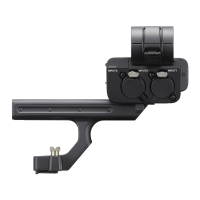
各部の名前
1 INPUT3端子(ステレオミニジャック、プラグインパワー対応)
2 リリースレバー
3 INPUT2端子(XLR/TRS型3ピン、凹型、ファンタム電源対応)
4 INPUT1端子(XLR/TRS型3ピン、凹型、ファンタム電源対応)
5 マイクホルダー
6 ケーブルホルダー
7 マイクロUSB端子
8 取り付け用ネジ
9 マルチインターフェースフット
10 ATT(INPUT1)スイッチ
11 INPUT1(LINE/MIC/MIC+48V)スイッチ
12 ATT(INPUT2)スイッチ
13 INPUT2(LINE/MIC/MIC+48V)スイッチ
14
LOWCUT(INPUT1)スイッチ
15 AUTO/MAN(INPUT3)スイッチ
16 AUTO/MAN(INPUT1)スイッチ
17
AUDIOLEVEL(INPUT1)ダイヤル
18 AUTO/MAN/LINK(INPUT2)スイッチ
19
AUDIOLEVEL(INPUT2)ダイヤル
20 LOWCUT(INPUT2)スイッチ
21 AUDIOLEVEL(INPUT3)ダイヤル
22 INPUTSELECTスイッチ
23 HANDLEAUDIOスイッチ
ご注意
• INPUT1端子/INPUT2端子に外部マイクや外部機器を取り付けたり、取り外し
たりするときは、必ずINPUT1(LINE/MIC/MIC+48V)/INPUT2(LINE/MIC/
MIC+48V)スイッチを「MIC+48V」以外に切り替えてください。「MIC+48V」のま
まケーブルの抜き差しを行うと、大きなノイズが出たり、外部マイクや外部機
器が故障したりする可能性があります。
• 録音中はカメラやレンズの作動音、操作音などが記録されてしまうことがあり
ます。録音中に本機に触れると、ノイズとして録音されてしまいます。
• 録音中は、INPUT1スイッチ、INPUT2スイッチの設定を変更しないでください。
• 使用中、マイクをスピーカーに近づけると「ピー」という音が発生することがあ
ります(ハウリング現象)。その場合は、マイクとスピーカーの距離をできるだ
け離すか、スピーカーの音量を下げてください。
• マイクにほこりや水滴などが付着していると、正しく録音されないことがあり
ます。取り除いてから使用してください。
• 取り付け/取り外しの際には、カメラの電源をオフにしてください。
•
本機をカメラに接続しているとき、HANDLEAUDIOスイッチがONのときはカ
メラ側の内蔵マイクの入力音声を録音することはできません。
• 本機を取り付けるときは、ハンドル取り付けネジ2本を確実に締めてください。
ハンドル取り付けネジを締めずに使用すると、マルチインターフェースシュー
端子の破損や本機が落下するおそれがあります。
カメラに本機を取り付ける
カメラに本機を取り付けると、同時に4系統の音声機器をカメラに接続すること
ができます。
1
カメラの電源スイッチをオフにする
2
カメラからシューキャップ、本機からハンドルシューキャップをそ
れぞれ外す
3
本機をマルチインターフェースシューにスライドさせて奥まで差し
込み、コインなどを使って、2つのネジ(a)を必ず確実に締めて固定す
る
使い方などの詳細は、カメラのヘルプガイドをご覧ください。
主な仕様
外形寸法(約) 113.2mm×140.8mm×172mm(幅/高さ/奥行き)
(突起物含まず)
質量(約) 305g
同梱物 XLRハンドルユニット(1)、
ハンドルシューキャップ(1)(本機に装着)、印刷物一式
仕様および外観は、改良のため予告なく変更することがありますが、ご了承くだ
さい。
MultiInterfaceShoe(マルチインターフェースシュー)はソニーグループ株式会
社の商標です。
保証書とアフターサービス
保証書
• この製品には保証書が添付されていますので、お買い上げの際、お受け取りく
ださい。
• 所定事項の記入および記載内容をお確かめのうえ、大切に保管してください。
アフターサービス
調子が悪いときはまずチェックを
この取扱説明書をもう一度ご確認ください。それでも具合が悪いときは相談窓口
にご相談ください。
保証期間中の修理は
保証書の記載内容に基づいて修理させていただきます。詳しくは保証書をご覧く
ださい。
保証期間経過後の修理は
修理によって機能が維持できる場合は、ご要望により有料修理させていただきま
す。
部品の保有期間について
当社はカメラの補修用性能部品(製品の機能を維持するために必要な部品)を製
造打ち切り後7年間保有しています。ただし、故障の状況、その他の事情により、修
理に代えて製品を交換する場合がありますので、ご了承ください。
ご相談になるときは次のことをお知らせください。
• 型名:XLR-H1
• 故障の状態:できるだけ詳しく
• お買い上げ年月日
Notes on use
• For camera models compatible with this unit, visit
the following website.
In combination with any camera model
manufactured by Sony that is not listed on the
website, the unit does not work.
https://www.sony.net/dics/h1/
• Using this unit with products from other manufacturers may affect its
performance, leading to accidents or malfunction.
• This unit is not dust-proof, splash-proof, or waterproof.
• To avoid the risk of a fire or an electric shock, observe the following:
– Do not disassemble or alter this unit.
– Do not use this unit with wet hands.
– Do not allow ingress of water or foreign matters (metal, flammable
substances, etc.) to this unit.
– Do not use this unit in a place subject to water splashes, high
humidity, dust, oil fumes, and steam.
• To avoid the risk of damage or a malfunction, observe the following:
– This unit is precision equipment. Do not drop the unit, hit it, or
subject it to a strong physical impact.
– Do not touch the electrical contacts on this unit with bare hands.
– Do not use or store this unit in a place subject to high temperatures
and humidity.
– When using this unit outdoors, keep the unit from exposure to rain
or seawater.
• For interior inspection and repair of this unit, contact your Sony
dealer or local authorized Sony service facility.
For Customers in the U.S.A.
For question regarding your product or for the Sony Service Center
nearest you, call 1-800-222-SONY (7669).
Supplier’s Declaration of Conformity
Trade Name : SONY
Model : XLR-H1
Responsible Party : Sony Electronics Inc.
Address : 16535 Via Esprillo, San Diego, CA 92127 U.S.A.
Telephone Number : 858-942-2230
Identifying the Parts
1 INPUT3 jack (stereo mini-jack, plug-in-power compatible)
2 Release lever
3 INPUT2 jack (3-pin XLR/TRS, female type, phantom-power
compatible)
4 INPUT1 jack (3-pin XLR/TRS, female type, phantom-power
compatible)
5 Microphone holder
6 Cable holder
7 Micro USB port
8 Attachment screws
9 Multi Interface foot
10 ATT (INPUT1) switch
11 INPUT1 (LINE/MIC/MIC+48V) switch
12 ATT (INPUT2) switch
13 INPUT2 (LINE/MIC/MIC+48V) switch
14 LOW CUT (INPUT1) switch
15 AUTO/MAN (INPUT3) switch
16 AUTO/MAN (INPUT1) switch
17 AUDIO LEVEL (INPUT1) dial
18 AUTO/MAN/LINK (INPUT2) switch
19 AUDIO LEVEL (INPUT2) dial
20 LOW CUT (INPUT2) switch
21 AUDIO LEVEL (INPUT3) dial
22 INPUT SELECT switch
23 HANDLE AUDIO switch
Notes
• Before connecting/disconnecting an external microphone or device
to/from the INPUT1 or INPUT2 jack, be sure to set the INPUT1 (LINE/
MIC/MIC+48V) or INPUT2 (LINE/MIC/MIC+48V) switch to a position
other than “MIC+48V.” Plugging/unplugging the cable into/from the
external microphone or device while the switch is set to “MIC+48V”
may cause loud noise or a malfunction of the device.
• While recording is in progress, operating and handling noises
from the camera or lens may be recorded. Touching this unit while
recording is in progress will cause noise to be included in the
recording.
• While recording is in progress, do not change the INPUT1 or INPUT2
switch settings.
• If the microphone of this unit is in proximity to a speaker, acoustic
feedback may occur. In this case, move the unit away from the
speaker to allow the maximum distance between the microphone
and the speaker, or lower the speaker volume.
• If dust or water droplets are present on the surface of the
microphone, successful recording may not be possible. Be sure to
clean the microphone surface before using this unit.
• Turn off the camera before attaching/removing this unit.
• When this unit is connected to the camera and the HANDLE AUDIO
switch is set to ON, the internal microphone of the camera cannot
record audio input.
• When attaching this unit to the camera, fasten the two handle-
attachment screws securely. Using this unit without fastening the
handle-attachment screws may damage the Multi Interface Shoe
terminal or cause the unit to fall off.
Attaching this unit to the camera
By attaching this unit, up to four audio devices can be connected to the
camera simultaneously.
1 Set the power switch of the camera to off.
2 Remove the shoe cap from the camera and the handle
shoe cap from this unit.
3 Slide this unit into the Multi Interface Shoe until it reaches
the back of the shoe.
Then, be sure to securely tighten the screws (a) on either
side using a coin, etc.
For more information, refer to the Help Guide provided for the
camera.
Specifications
Dimensions (Approx.) 113.2 mm × 140.8 mm × 172 mm
(4 1/2 in. × 5 5/8 in. × 6 7/8 in.) (W/H/D)
(excluding the projecting parts)
Mass (Approx.) 305 g (10.8 oz)
Included items XLR handle unit (1),
Handle shoe cap (1) (attached to this unit),
Set of printed documentation
Design and specifications are subject to change without notice.
“Multi Interface Shoe” is a trademark of Sony Group Corporation.
Remarques sur l’emploi
• Pour savoir les modèles d’appareil photo
compatibles avec cet accessoire, consultez le site
internet suivant.
Cet accessoire ne fonctionne pas sur un modèle
d’appareil photo fabriqué par Sony qui n’est pas
répertorié sur le site internet.
https://www.sony.net/dics/h1/
• L’utilisation de cet appareil avec des produits d’autres fabricants
risque de nuire à ses performances, entraînant des accidents ou des
dysfonctionnements.
• Cet accessoire n’est pas étanche à la poussière, aux éclaboussures
d’eau ou à l’eau.
• Pour éviter tout risque d'incendie ou d'électrocution, observez les
points suivants :
– Ne démontez ni ne modifiez pas cet accessoire.
– N'utilisez pas cet accessoire avec les mains mouillées.
– Ne faites pas pénétrer de l'eau ou des corps étrangers (métal,
matières inflammables, etc.) à l'intérieur de cet accessoire.
– N'utilisez pas cet accessoire dans un endroit exposé à des
éclaboussements d'eau, un taux d'humidité élevé, des poussières,
des émanations d'huile et la vapeur.
• Pour éviter tout risque d'endommagement ou de
dysfonctionnement, observez les points suivants :
– Cet accessoire est un dispositif de précision. Ne le laissez pas
tomber ou ne le heurtez pas ; évitez également qu'il subisse un
choc physique violent.
– Ne touchez pas les contacts électriques de cet accessoire à mains
nues.
– N'utilisez ni ne rangez pas cet accessoire à un endroit exposé à des
températures ou un taux d'humidité élevés.
– Lors de l'utilisation de cet accessoire à l'extérieur, évitez toute
exposition à la pluie ou l'eau de mer.
• Pour réaliser une réparation ou inspection à l'intérieur de cet
accessoire, contactez le distributeur Sony ou le centre de service Sony
agréé le plus proche.
Identification des éléments
1 Prise INPUT3 (mini-jack stéréo, compatible entrée alimentée)
2 Levier de déverrouillage
3 Prise INPUT2 (XLR/TRS à 3 broches, type femelle, compatible
alimentation fantôme)
4 Prise INPUT1 (XLR/TRS à 3 broches, type femelle, compatible
alimentation fantôme)
5 Porte-microphone
6 Porte-câble
7 Port micro USB
8 Vis de fixation
9 Connecteur de griffe multi-interface
10 Commutateur ATT (INPUT1)
11 Commutateur INPUT1 (LINE/MIC/MIC+48V)
12 Commutateur ATT (INPUT2)
13 Commutateur INPUT2 (LINE/MIC/MIC+48V)
14 Commutateur LOW CUT (INPUT1)
15 Commutateur AUTO/MAN (INPUT3)
16 Commutateur AUTO/MAN (INPUT1)
17 Sélecteur AUDIO LEVEL (INPUT1)
18 Commutateur AUTO/MAN/LINK (INPUT2)
19 Sélecteur AUDIO LEVEL (INPUT2)
20 Commutateur LOW CUT (INPUT2)
21 Sélecteur AUDIO LEVEL (INPUT3)
22 Commutateur INPUT SELECT
23 Commutateur HANDLE AUDIO
Remarques
• Avant de connecter/déconnecter un microphone ou un
appareil externe sur/de la prise INPUT1 ou INPUT2, veillez
à placer le commutateur INPUT1 (LINE/MIC/MIC+48V) ou
INPUT2 (LINE/MIC/MIC+48V) sur une position autre que « MIC+48V ».
Si vous branchez ou débranchez le câble sur/dans le microphone ou
l’appareil externe alors que le commutateur est placé sur « MIC+48V »,
cela peut provoquer des bruits forts ou un dysfonctionnement de
l’appareil.
• Pendant qu'un enregistrement est en cours, les bruits provoqués par
l'utilisation ou la manipulation de l'appareil photo ou de l’objectif
peuvent être enregistrés. Du bruit sera enregistré si vous touchez cet
accessoire pendant un enregistrement.
• Pendant l’enregistrement, ne changez pas les réglages INPUT1 ou INPUT2
du commutateur.
• Si le microphone de cet accessoire est placé près d’une enceinte, un
effet Larsen peut se produire. Dans ce cas, éloignez le plus possible
l'accessoire de l'enceinte en fonction de la distance maximale
autorisée entre le microphone et l'enceinte, ou baissez le volume de
l'enceinte.
• Si des grains de poussière ou des gouttelettes d'eau se trouvent
sur la surface du microphone, la qualité d'enregistrement risque
de ne pas être optimale. Assurez-vous de nettoyer la surface du
microphone avant d'utiliser cet accessoire.
• Éteignez l’appareil photo avant de fixer ou de retirer cet accessoire.
• Lorsque cet accessoire est connecté à l’appareil photo et que le
commutateur HANDLE AUDIO est réglé sur ON, le microphone interne
de l’appareil photo ne peut pas enregistrer l’entrée audio.
• Lors de la fixation de cet accessoire sur l’appareil photo, vissez à fond
les deux vis de fixation de la poignée. L'utilisation de cet accessoire
sans serrer les vis de fixation de la poignée peut endommager la
borne du sabot multi-interface ou faire tomber l’accessoire.
Fixation de cet accessoire sur un
appareil photo
En fixant cet accessoire, jusqu’à quatre périphériques audio peuvent
être raccordés simultanément à l’appareil photo.
1 Mettez l’interrupteur d’alimentation de l’appareil photo en
position éteint.
2 Retirez le capuchon de la griffe de l’appareil photo et le
cache de la griffe de la poignée de cet accessoire.
3 Faites glisser cet accessoire à fond dans la griffe multi-
interface.
Assurez-vous ensuite de serrer à fond les vis (a) de chaque
côté à l’aide d'une pièce de monnaie par exemple.
Pour plus d’informations, reportez-vous au Guide d’aide de
l’appareil photo.
Spécifications
Dimensions (environ) 113,2 mm × 140,8 mm × 172 mm
(4 1/2 po. × 5 5/8 po. × 6 7/8 po.) (L/H/P)
(parties saillantes non comprises)
Poids (environ) 305 g (10,8 oz)
Articles inclus poignée XLR (1),
cache de la griffe de la poignée (1) (fixé à cet
accessoire),
jeu de documents imprimés
La conception et les spécifications peuvent être modifiées sans préavis.
« Multi Interface Shoe » est une marque commerciale de
Sony Group Corporation.
Notas sobre la utilización
• Para los modelos de cámara compatibles con esta
unidad, visite el sitio web siguiente.
La unidad no funcionará en combinación con ningún
modelo de cámara fabricada por Sony que no figure
en el sitio web.
https://www.sony.net/dics/h1/
• El uso de esta unidad con productos de otros fabricantes
puede afectar a su rendimiento, provocando accidentes o mal
funcionamiento.
• Esta unidad no es resistente al polvo, las salpicaduras, ni el agua.
• Para evitar riesgos, como un incendio o una descarga eléctrica,
observe lo siguiente:
– No desarme ni modifique esta unidad.
– No utilice esta unidad con las manos húmedas.
– No permita la entrada de agua ni materias extrañas (metal,
sustancias inflamables, etc.) en esta unidad.
– No utilice esta unidad en un lugar sujeto a salpicaduras de agua,
alta humedad, polvo, humos de aceite, y vapor.
• Para evitar el riesgo de daños o un mal funcionamiento, observe lo
siguiente:
– Esta unidad es un equipo de precisión. No deje caer la unidad, no la
golpee, ni la someta a un fuerte impacto físico.
– No toque los contactos eléctricos de esta unidad con las manos
desnudas.
– No utilice ni almacene esta unidad en un lugar sujeto a altas
temperaturas y humedad.
– Cuando utilice esta unidad al aire libre, evite exponerla a la lluvia o
al agua de mar.
• Para la inspección y reparación interior de esta unidad, póngase
en contacto con su distribuidor Sony o con el servicio técnico local
autorizado por Sony.
Identificación de los componentes
1 La toma INPUT3 (minitoma estéreo, compatible con alimentación
por enchufe)
2 Palanca de liberación
3 Toma INPUT2 (XLR/TRS de 3 pines, tipo hembra, compatible con
alimentación phantom)
4 Toma INPUT1 (XLR/TRS de 3 pines, tipo hembra, compatible con
alimentación phantom)
5 Soporte de micrófono
6 Soporte de cable
7 Puerto micro USB
8 Tornillos de sujeción
9 Zapata de interfaz múltiple
10 Interruptor ATT (INPUT1)
11 Interruptor INPUT1 (LINE/MIC/MIC+48V)
12 Interruptor ATT (INPUT2)
13 Interruptor INPUT2 (LINE/MIC/MIC+48V)
14 Interruptor LOW CUT (INPUT1)
15 Interruptor AUTO/MAN (INPUT3)
16 Interruptor AUTO/MAN (INPUT1)
17 Dial AUDIO LEVEL (INPUT1)
18 Interruptor AUTO/MAN/LINK (INPUT2)
19 Dial AUDIO LEVEL (INPUT2)
20 Interruptor LOW CUT (INPUT2)
21 Dial AUDIO LEVEL (INPUT3)
22 Interruptor INPUT SELECT
23 Interruptor HANDLE AUDIO
Notas
• Antes de conectar o desconectar un micrófono o dispositivo externo
a/de la clavija INPUT1 o INPUT2, asegúrese de ajustar el interruptor
INPUT1 (LINE/MIC/MIC+48V) o INPUT2 (LINE/MIC/MIC+48V) a una
posición distinta de “MIC+48V”. Enchufar o desenchufar el cable
en el micrófono o dispositivo externo mientras el interruptor esté
ajustado en “MIC+48V” podrá ocasionar un ruido fuerte o un mal
funcionamiento del dispositivo.
• Mientras la grabación esté en curso, se pueden grabar los ruidos de
operación y manejo de la cámara o el objetivo. Tocar esta unidad
mientras la grabación esté en curso hará que se incluya ruido en la
grabación.
• Durante la grabación, no cambie los ajustes del interruptor INPUT1 ni
INPUT2.
• Si el micrófono de esta unidad está cerca de un altavoz, puede ocurrir
retroalimentación acústica. En tal caso, aleje la unidad del altavoz
para permitir la distancia máxima entre el micrófono y el altavoz,
o reduzca el volumen del altavoz.
• Si hay polvo o gotas de agua en la superficie del micrófono, puede
que no sea posible realizar una grabación exitosa. Asegúrese de
limpiar la superficie del micrófono antes de utilizar esta unidad.
• Apague la cámara antes de fijar/retirar esta unidad.
• Cuando esta unidad esté conectada a la cámara y el interruptor
HANDLE AUDIO esté en ON, el micrófono interno de la cámara no
podrá grabar entrada de audio.
• Cuando fije esta unidad a la cámara, apriete bien los dos tornillos de
sujeción del asa. La utilización de esta unidad sin apretar los tornillos
de sujeción del asa puede dañar el terminal de la zapata de interfaz
múltiple o hacer que la unidad se caiga.
Fijación de esta unidad a la cámara
Al fijar esta unidad, podrán conectarse hasta cuatro dispositivos de
audio simultáneamente a la cámara.
1 Ponga el interruptor de alimentación de la cámara en
desconexión.
2 Retire la tapa de la zapata de la cámara y la tapa de la
zapata del asa de esta unidad.
3 Deslice esta unidad en la zapata de interfaz múltiple hasta
que alcance la parte posterior de la zapata.
Después, asegúrese de apretar bien los tornillos (a) de
ambos lados utilizando una moneda, etc.
Para más información, consulte la Guía de ayuda proporcionada
para la cámara.
Especificaciones
Dimensiones (Aprox.) 113,2 mm × 140,8 mm × 172 mm (An/Al/Pr)
(excluyendo las partes salientes)
Peso (Aprox.) 305 g
Elementos incluidos Unidad de mano XLR (1),
Tapa de la zapata del asa (1) (fijada a esta
unidad),
Juego de documentación impresa
El diseño y las especificaciones están sujetos a cambio sin previo aviso.
“Multi Interface Shoe” es marca comercial de Sony Group Corporation.
Hinweise zur Verwendung
• Bezüglich Kameramodellen, die mit diesem Gerät
kompatibel sind, besuchen Sie die folgende
Website.
In Kombination mit einem von Sony hergestellten
Kameramodell, das nicht auf der Website aufgeführt
ist, funktioniert das Gerät nicht.
https://www.sony.net/dics/h1/
• Verwendung dieses Geräts mit Produkten anderer Hersteller kann
seine Leistung beeinträchtigen, was zu Unfällen oder Fehlfunktionen
führen kann.
• Dieses Gerät ist nicht staubdicht, spritzfest oder wasserfest
konstruiert.
• Um Gefahren wie Brände oder elektrische Schläge zu vermeiden,
beachten Sie Folgendes:
– Zerlegen oder modifizieren Sie das Gerät nicht.
– Verwenden Sie dieses Gerät nicht mit nassen Händen.
– Vermeiden Sie Eindringen von Wasser oder Fremdmaterialien
(Metall, brennbare Substanzen usw.) in dieses Gerät.
– Verwenden Sie dieses Gerät nicht an einem Ort, der
Wasserspritzern, hoher Luftfeuchtigkeit, Staub, Öldämpfen und
Dampf ausgesetzt ist.
• Um Gefahren wie Schäden oder Fehlfunktionen zu vermeiden,
beachten Sie Folgendes:
– Dieses Gerät ist eine Präzisionsausrüstung. Lassen Sie das Gerät
nicht fallen, stoßen Sie es nicht an und setzen Sie es keinen starken
physischen Einwirkungen aus.
– Berühren Sie nicht die elektrischen Kontakte am Gerät mit bloßen
Händen.
– Verwenden oder lagern Sie dieses Gerät nicht an einem Ort, der
hohen Temperaturen und Feuchtigkeit ausgesetzt ist.
– Wenn Sie dieses Gerät im Freien verwenden, halten Sie es von
Regen oder Meerwasser fern.
• Wenden Sie sich für die Prüfung des Inneren und Reparatur dieses
Geräts an Ihren Sony-Händler oder eine örtliche autorisierte
Sony-Kundendienstvertretung.
Identifikation der Teile
1 Buchse INPUT3 (Stereo-Minibuchse, mit Plug-in-Power kompatibel)
2 Freigabehebel
3 Buchse INPUT2 (3-polige XLR/TRS-Buchse, mit Phantomspeisung
kompatibel)
4 Buchse INPUT1 (3-polige XLR/TRS-Buchse, mit Phantomspeisung
kompatibel)
5 Mikrofonhalter
6 Kabelhalter
7 Micro-USB-Anschluss
8 Befestigungsschrauben
9 Multi-Interface-Fuß
10 Schalter ATT (INPUT1)
11 Schalter INPUT1 (LINE/MIC/MIC+48V)
12 Schalter ATT (INPUT2)
13 Schalter INPUT2 (LINE/MIC/MIC+48V)
14 Schalter LOW CUT (INPUT1)
15 Schalter AUTO/MAN (INPUT3)
16 Schalter AUTO/MAN (INPUT1)
17 Drehrad AUDIO LEVEL (INPUT1)
18 Schalter AUTO/MAN/LINK (INPUT2)
19 Drehrad AUDIO LEVEL (INPUT2)
20 Schalter LOW CUT (INPUT2)
21 Drehrad AUDIO LEVEL (INPUT3)
22 Schalter INPUT SELECT
23 Schalter HANDLE AUDIO
Hinweise
• Bevor Sie ein externes Mikrofon oder ein Gerät an die Buchse
INPUT1 oder INPUT2 anschließen bzw. von ihr abtrennen,
sollten Sie den Schalter INPUT1 (LINE/MIC/MIC+48V) oder
INPUT2 (LINE/MIC/MIC+48V) unbedingt auf eine andere Position
als „MIC+48V“ stellen. Wird das Kabel an das externe Mikrofon
oder Gerät angeschlossen bzw. davon abgetrennt, während der
Schalter auf „MIC+48V“ steht, kann ein lautes Geräusch oder eine
Funktionsstörung des Gerätes verursacht werden.
• Während der Aufnahme können von der Kamera oder dem Objektiv
erzeugte Betriebs- und Handhabungsgeräusche aufgezeichnet
werden. Wenn Sie dieses Gerät bei laufender Aufnahme berühren,
wird Rauschen in der Aufnahme verursacht.
• Ändern Sie bei laufender Aufnahme nicht die Einstellungen des
Schalters INPUT1 oder INPUT2.
• Wenn sich das Mikrofon dieses Geräts in der Nähe eines
Lautsprechers befindet, kann akustische Rückkopplung auftreten.
Bewegen Sie in diesem Fall das Gerät weiter vom Lautsprecher
weg, um den maximalen Abstand zwischen dem Mikrofon und
dem Lautsprecher zu ermöglichen; oder verringern Sie die
Lautsprecherlautstärke.
• Wenn sich Staub oder Wassertröpfchen auf der Oberfläche des
Mikrofons befinden, ist erfolgreiche Aufnahme möglicherweise nicht
möglich. Reinigen Sie vor der Verwendung dieses Geräts unbedingt
die Mikrofonoberfläche.
• Schalten Sie die Kamera aus, bevor Sie dieses Gerät anbringen/
abnehmen.
• Wenn dieses Gerät mit der Kamera verbunden ist und der Schalter
HANDLE AUDIO auf ON gestellt ist, kann das eingebaute Mikrofon der
Kamera den Audio-Eingang nicht aufzeichnen.
• Beim Anbringen dieses Geräts an die Kamera befestigen Sie die
beiden Griff-Befestigungsschrauben sicher. Die Verwendung dieses
Geräts ohne Befestigung der Griff-Befestigungsschrauben kann die
Multi-Interface-Schuh-Klemme beschädigen oder dazu führen, dass
das Gerät herunterfällt.
Anbringen des Geräts an der
Kamera
Indem Sie dieses Gerät anbringen, können bis zu vier Audiogeräte
gleichzeitig an die Kamera angeschlossen werden.
1 Stellen Sie den Ein-Aus-Schalter der Kamera auf Aus.
2 Nehmen Sie die Schuhkappe von der Kamera und die
Kappe für den Schuh am Griff von diesem Gerät ab.
3 Schieben Sie dieses Gerät in den Multi-Interface-Schuh, bis
es die Rückseite des Schuhs erreicht.
Stellen Sie dann sicher, die Schrauben (a) auf beiden Seiten
mit einer Münze o.ä. sicher festzuziehen.
Weitere Informationen finden Sie in der Hilfe für die Kamera.
Technische Daten
Abmessungen (ca.) 113,2 mm × 140,8 mm × 172 mm (B/H/T)
(ohne vorstehende Teile)
Gewicht (ca.) 305 g
Mitgeliefertes Zubehör XLR-Griff (1),
Kappe für den Schuh am Griff (1) (angebracht
an diesem Gerät),
Anleitungen
Änderungen, die dem technischen Fortschritt dienen, bleiben
vorbehalten.
„Multi Interface Shoe“ ist ein Warenzeichen der
Sony Group Corporation.
5
6
8