Registered Quality System to ISO 9001:2008
24/60
Form 912
sorinc.com
913-888-2630
401 A-G3A-B-A1-N4-CRTT
Select a process connection designator from the chart below based on style and size. Consult the factory for
variations. 3” flanged process connections may require the float to be installed from inside the process connection.
Select the internal trim material from the chart below. Consult the factory for pressure ratings on Monel trim.
401 A-G3A-B-A1-N4-CRTT
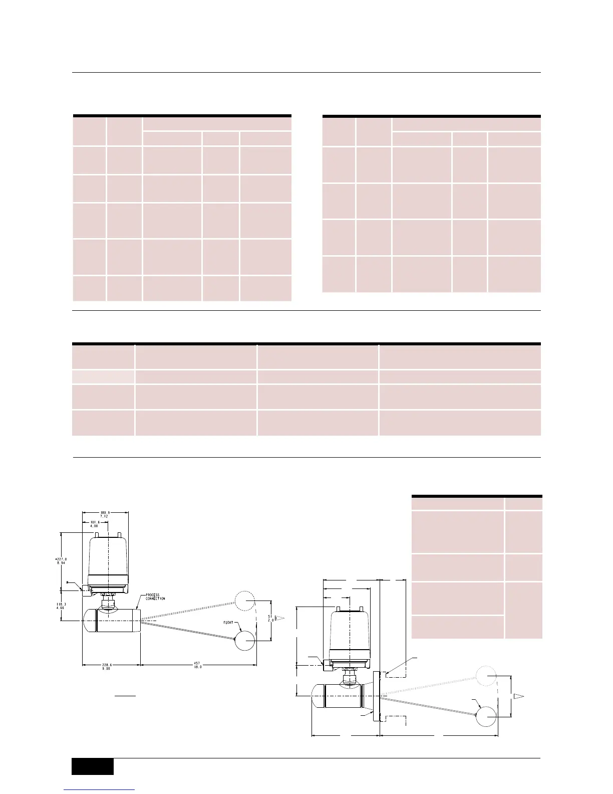
Dimensions in this catalog are for reference only. They may be changed without notice. Contact the factory
for certified drawings for a particular model number. Dimensions are expressed as millimeters over inches.
(Linear = mm/in.)
Step 3: Process Connection
Step 4: Trim Material
Chamber Dimensions
400 Series
Model
Float
Size
Connection
Designator Size Style
405 3 x 6” G3G 3”
300# RF
Weld Neck
Flange
405 3 x 6” G4G 4”
300# RF
Weld Neck
Flange
406 3 x 6” G3H 3”
600# RF
Weld Neck
Flange
406 3 x 6” G4H 4”
600# RF
Weld Neck
Flange
Designator Float Material Attraction Sleeve
Available with
Chamber Material:
B 316/316L Stainless Steel 400 Stainless Steel A106 Carbon Steel (A) only
C 316/316L Stainless Steel 316/316L Stainless Steel
A106 Carbon Steel (A) or 316/316L
Stainless Steel (C)
M Monel 400 Monel 400
A106 Carbon Steel (A) or 316/316L
Stainless Steel (C)
Model
Float
Size
Connection
Designator Size Style
401 3” G3A 3”
NPT(M)
Thread
402 2-1/2” G7A 2-1/2”
NPT(M)
Thread
403 3” G3F 3”
150# RF
Weld Neck
Flange
403 3” G4F 4”
150# RF
Weld Neck
Flange
404 3 x 6” G3A 3”
NPT(M)
Thread
* Minimum
146.1
overhead clearance required to remove
housing cover.
5.75
** See Housing section (page 48).
*** M20 adapters are brass. Contact the factory for alternate
materials.
Models 403, 405, 406
ISO-9001
14685 W 105TH ST LENEXA, KS 66215 USA
913-888-2630
SORINC.COM
D
457
18.0
N
118.3
4.66
101.6
4.00
180.9
7.12
*227.0
8.94
FLOAT
263.5
10.38
217.5
8.56
FLANGED
UNITS
MODEL
51
2.0
102
4.0
152
6.0
203
8.0
254
10.0
403
330
13.0
405**
152
6.0
406**
STANDARD DIFFERENTIAL (D)
MODEL "D" @ MIN. S.G.
403
51
2.0
405
44.5
1.75
406
Model Name: 0390669.ASSEM/1/5+
PRODUCT CERTIFICATION DRAWING
ALL DIMENSIONS ARE ±1/16 IN
UNLESS OTHERWISE SPECIFIED
MM
LINEAR =
IN
DRAWN BY
K MITCHELL
CHECKED BY
J REHM
ENGINEER APPROVAL
J FIFE
DATE
08 APR 2011
THIS DRAWING IS THE EXCLUSIVE PROPERTY OF SOR.
NO USE WHATSOEVER OF THE INFORMATION CONTAINED
HEREON, NOR REPRODUCTION IN WHOLE OR PART MAY BE
MADE WITHOUT THE EXPRESS WRITTEN PERMISSION OF SOR.
TITLE
DIM DWG 403,405,406
FLOAT OPERATED
EO NUMBER: 5090
SCALE: 0.33
DO NOT SCALE PRINT
DRAWING NUMBER REV
0390669 2
SHEET 1 OF 1
DWG SIZE
B
MODEL # SALES ORDER # LINE ITEM # PURCHASE ORDER #
146.1
* MINIMUM OVERHEAD CLEARANCE
5.75
REQUIRED TO REMOVE HOUSING COVER.
**BASED ON 4" FLANGE SIZE
NOTES:
1. STANDARD DIFFERENTIAL. FOR MAXIMUM DIFFERENTIAL, SEE TABLE.
ELECTRICAL CONN. "W" : __________
PROCESS
CONNECTION
WELD NECK
FLANGE
CUSTOMER
PROCESS
CONNECTION
W
1
1
Drawing
0390669
Housing** W
General Purpose
Explosion Proof
Explosion Proof
Explosion Proof
N4
N7
B1
B2
1” NPT
Pneumatic P1
(3) 1/4”
NPT
ATEX
Flame Proof/IS
T6
S3
w/CL
M20 x
1.5***
TestSafe
Flame Proof
S3
S8
Models 401, 402, 404
Drawing
0390668
 Loading...