Registered Quality System to ISO 9001:2008
25/60
Form 912
sorinc.com
913-888-2630
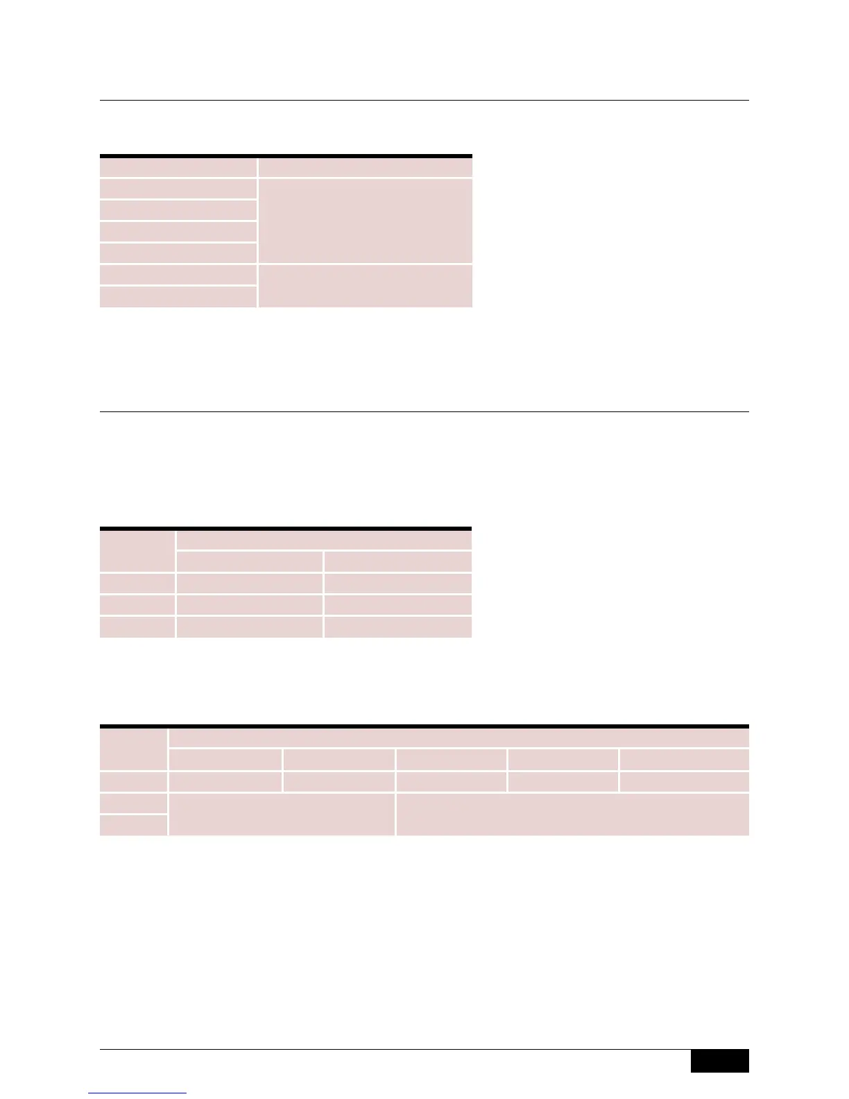
Calibration Dimensions
Maximum Differential (D)
Differential Dimension “D” is calibrated to the minimum shown above as standard. Wider
differentials are available by placing an SC in the accessory section of the model number.
The charts below give the maximum differentials available.
Standard Differential (D)
NPT Units
Flanged Units
Note: With anti-vibration, extra-high
temperature and pneumatic switch,
minimum differential will increase.
*Based on 4-inch flange size.
400 Series
Model “D” @ Minimum Specific Gravity
401
3” (76 mm)
402
403
404
405
2-3/4” (70 mm)
406
Model
Customer Mounting
1/2 Coupling Full Coupling
401 12-3/8” (356 mm) 10-1/4” (292 mm)
402 8-7/8” (292 mm) 8-7/8” (292 mm)
404 12-3/8” (356 mm) 10-1/4” (292 mm)
Model
Customer Nozzle Length (N)
2” (51 mm) 4” (102 mm) 6” (152 mm) 8” (203 mm) 10” (254 mm)
403 13” (330 mm) 9” (229 mm) 7” (178 mm) 5” (127 mm) 4-1/2” (114 mm)
405*
6” (152 mm) 5” (127 mm)
406*
 Loading...