This document serves as an assembly and maintenance manual for the SOROTEC CNC portal milling machine kit, specifically the Alu-Line series. It provides detailed instructions for assembling the machine, along with technical specifications and maintenance guidelines.
The Alu-Line series comprises several models, including the ALU 0605, ALU 0607, ALU 0610, ALU 1105, ALU 1107, ALU 1110, and their "HEAVY" and "HEAVY GANTRY" variants. These machines are designed for CNC portal milling applications, offering various travel ranges and clamping surface dimensions to suit different operational needs.
Function Description:
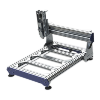
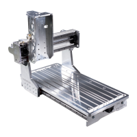
The SOROTEC Alu-Line CNC portal milling machine is a kit-based system designed for precision milling operations. It utilizes a portal design, where the milling head moves along X, Y, and Z axes to perform machining tasks. The machine's core function is to accurately position a milling spindle (an optional accessory) relative to a workpiece, allowing for material removal and shaping according to programmed instructions. The assembly instructions guide users through the construction of the machine's mechanical components, including the base frame, portal, and Z-axis, which together form the rigid structure necessary for precise milling. The system relies on ball screws and linear guides for smooth and accurate motion along each axis.
Important Technical Specifications:
The technical specifications vary across the Alu-Line models, but common features include:
- Travel (X | Y | Z): Ranges from 650 | 550 | 220 mm for the ALU 0605 to 2050 | 1350 | 220 mm for the ALU 2013 HEAVY. The Z-axis travel is consistently 220 mm across all models.
- Clamping Surface (X | Y): Varies from 1000 | 550 mm to 2400 | 1350 mm, providing ample space for different workpiece sizes.
- Installation Dimensions (L | B | H): The footprint of the machines ranges from 1050 | 960 | 1080 mm to 2450 | 1760 | 1080 mm.
- Passage Under Portal (Z): All models offer a Z-passage of 270 mm, allowing for machining of taller workpieces.
- Ball Screws:
- ALU-LINE: X: 16 x 10 mm | Y: 16 x 10 mm | Z: 16 x 5 mm, with tolerance class T07.
- ALU-LINE HEAVY/HEAVY GANTRY: X: 25 x 10 mm | Y: 16 x 10 mm | Z: 16 x 5 mm, with tolerance class T07.
- Repeatability: Approximately +/- 0.02 mm across all models, indicating high precision.
- Weight (w/o accessories): Ranges from approximately 95 kg for the ALU 0605 to 270 kg for the ALU 2013 HEAVY.
- Linear Guides: HIWIN linear guides 20 mm with medium preload carriages, manufactured to special specifications for HIWIN Germany.
- Clamping Surface: Optionally available with aluminum T-slot plate or screen printing plate.
- Software Parameters (Steps / Revolution | Steps / mm):
- X: 3200 | Y: 3200 | Z: 3200 (with power stage set to 3200 microsteps).
- X: 320 | Y: 320 | Z: 640.
- Max Feed Speed: X: 150 mm/s or 9 m/min | Y: 150 mm/s or 9 m/min | Z: 83 mm/s or 5 m/min.
- Acceleration (mm/s²): X: 300 | Y: 300 | Z: 200 (with 48 V supply voltage and high-quality power amplifiers).
Usage Features:
The Alu-Line kit is designed for users to assemble their own CNC portal milling machine. Key usage features include:
- Modular Design: The kit-based approach allows for a structured assembly process, guided by detailed illustrations and step-by-step instructions.
- Precision Assembly: Emphasis is placed on careful and exact assembly, as the accuracy of the finished machine is highly dependent on the quality of assembly and alignment of components.
- Component Verification: Users are instructed to check all components for burrs and rework them if necessary before assembly, ensuring optimal performance.
- Optional Accessories: The machine can be customized and enhanced with a range of optional accessories, such as milling spindles, base frames, housings, vacuum tables, control electronics, control software, and minimum quantity lubrication, available from Sorotec. This allows users to tailor the machine to specific application requirements.
- Safety Guidelines: The manual includes a prominent warning to only carry out work if familiar with the necessary actions and tools, and Sorotec GmbH disclaims liability for damage or injury during assembly or operation.
- Specific Assembly Notes: Special instructions are provided for models with two ball screws on the X-axis, ensuring correct assembly for these configurations.
- Directional Consistency: All directions (left, right, front, back, up, and down) in the manual are based on a consistent viewing perspective shown in the figures.
- Measurement Guidance: An infosheet on measuring screws is included, detailing how to correctly measure screw dimensions (diameter and length) and providing examples. This is crucial for accurate assembly and component identification.
- Countersunk Screw Measurement: Specific guidance is given for measuring countersunk screws, where the head height is included in the total length.
- Bearing Assembly: Instructions for roller bearing assembly emphasize pressing/hitting only the outer bearing rings and using a suitable drive sleeve with oil to prevent damage.
- Axial Play Adjustment: Detailed steps are provided for adjusting the axial play of ball screws by tightening and slightly loosening shaft nuts until the ball screws turn easily.
- Linear Guide Alignment: The assembly aid (part of the scope of delivery) is used to align the lower linear guides on the profiles, ensuring they lie against the milled stop edges.
- Torque Specifications: Specific tightening torques are provided for various screws (e.g., 6 Nm for linear guide screws, 25 Nm for motor plate screws) to prevent distortion and ensure secure fastening.
- Reference Switch Installation: Instructions for installing reference switches include using insulation foil and specific screw types.
- Base Frame Alignment: A critical step involves adjusting the base frame to ensure parallelism and smooth movement of the portal, with instructions to loosen and gradually tighten screws while moving the portal.
- Stop Buffers: Self-adhesive device feet are used as stop buffers on the portal cheeks and guide plate.
Maintenance Features:
The manual includes a section on ball screw nut maintenance, drawing from ISEL instructions, which are crucial for the longevity and performance of the machine:
- Cleanliness: Ball screw nuts, spindles, and clamping blocks are precision components that require utmost cleanliness during handling and assembly.
- Lubrication:
- Pre-commissioning: The spindle must be thoroughly lubricated over its entire thread length before commissioning.
- Lubricant Type: Customary roller bearing oil and grease (sodium soap grease) should be used. Lubricants with graphite and MOS additives should be avoided.
- Lubrication Intervals:
- Oil Lubrication: Recommended for high spindle speeds (over 500 min-1), but requires shorter maintenance intervals (re-lubricate every 40 to 60 operating hours).
- Grease Lubrication: Offers advantages of independent installation position and longer lubrication intervals (300 to 700 operating hours) for rotational speeds up to approximately 800 min-1. About half of the nut volume should be filled with grease (GP00/000F-20 according to DIN 510502).
- Oil Viscosity Classes: A table provides recommended ISO viscosity classes (CLP ISO-VG) for spindles with a diameter of 16 mm, correlating average rotational speed with required viscosity at operating temperature.
- Protective Measures: Lubricated ball screws should be protected from dust, swarf, and moisture using wipers. Wipers are to be pushed into the grooves of the ball screw nut, with the notch positioned under the bore.
- Axial Backlash Adjustment: The running clearance between the nut and spindle should be adjusted using an adjusting screw, checking the clearance along the entire spindle.
- Radial Stress Prevention: The ball screw spindle must be installed free from radial stress, which is checked by moving the carriage back and forth while tightening the bearings.